
Laptop User Manual

9-24 Intel® PXA26x Processor Family Developer’s Manual
Inter-Integrated Circuit Bus Interface Unit
9.9.3 I
2
C Control Register- ICR
The processor uses the bits in the I
2
C Control Register (ICR) to control the I
2
C unit.
7:0 IDB
I
2
C DATA BUFFER:
Buffer for I
2
C bus send/receive data.
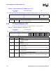
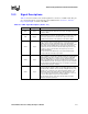
Table 9-10. I
2
C Data Buffer Register - IDBR (Sheet 2 of 2)
Physical Address
4030_1688
I
2
C Data Buffer Register I
2
C
Bit
31 30 29 28 27 26 25 24 23 22 21 20 19 18 17 16 15 14 13 12 11 10 9 8 7 6 5 4 3 2 1 0
Reserved
IDB
Reset 0 0 0 0 0 0 0 0 0 0 0 0 0 0 0 0 0 0 0 0 0 0 0 0 0 0 0 0 0 0 0 0
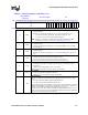
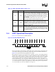
Table 9-11. I
2
C Control Register - ICR (Sheet 1 of 3)
Physical Address
4030_1690
I
2
C Control Register I
2
C
Bit
31 30 29 28 27 26 25 24 23 22 21 20 19 18 17 16 15 14 13 12 11 10 9 8 7 6 5 4 3 2 1 0
Reserved
FM
UR
SADIE
ALDIE
SSDIE
BEIE
IRFIE
ITEIE
GCD
IUE
SCLE
MA
TB
ACKNAK
STOP
START
Reset 0 0 0 0 0 0 0 0 0 0 0 0 0 0 0 0 0 0 0 0 0 0 0 0 0 0 0 0 0 0 0
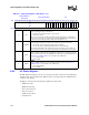
31:16 — Reserved
15 FM
FAST MODE:
0 – 100 KBit/sec. operation
1 – 400 KBit/sec. operation
14 UR
UNIT RESET:
0 – No reset.
1 – Reset the I
2
C unit only.
13 SADIE
SLAVE ADDRESS DETECTED INTERRUPT ENABLE:
0 – Disable interrupt.
1 – Enables the I
2
C unit to interrupt the processor when it detects a slave address match or
general call address.
12 ALDIE
ARBITRATION LOSS DETECTED INTERRUPT ENABLE:
0 – Disable interrupt.
1 – Enables the I
2
C unit to interrupt the processor when it loses arbitration in master mode.
11 SSDIE
SLAVE STOP DETECTED INTERRUPT ENABLE:
0 – Disable interrupt.
1 – Enables the I
2
C unit to interrupt the processor when it detects a STOP condition in
slave mode.