
S2600GZ and S2600GL


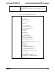
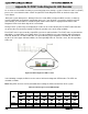
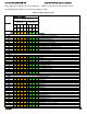
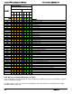
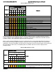
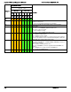
Table Of Contents
- 1. Introduction
- 2. Product Overview
- 3. Product Architecture Overview
- 3.1 Processor Support
- 3.2 Processor Functions Overview
- 3.2.1 Processor Core Features:
- 3.2.2 Supported Technologies:
- 3.2.3 Intel® QuickPath Interconnect
- 3.2.4 Integrated Memory Controller (IMC) and Memory Subsystem
- 3.2.4.1 Supported Memory
- 3.2.4.2 Memory Slot Identification and Population Rules
- 3.2.4.3 Publishing System Memory
- 3.2.4.4 Integrated Memory Controller Operating Modes
- 3.2.4.5 Memory RAS Support
- 3.2.5 Processor Integrated I/O Module (IIO)
- 3.3 Intel® C602 Chipset Functional Overview
- 3.4 Integrated Baseboard Management Controller Overview
- 4. System Security
- 5. Technology Support
- 6. Platform Management Functional Overview
- 6.1 Baseboard Management Controller (BMC) Firmware Feature Support
- 6.2 Advanced Configuration and Power Interface (ACPI)
- 6.3 Power Control Sources
- 6.4 BMC Watchdog
- 6.5 Fault Resilient Booting (FRB)
- 6.6 Sensor Monitoring
- 6.7 Field Replaceable Unit (FRU) Inventory Device
- 6.8 System Event Log (SEL)
- 6.9 System Fan Management
- 6.10 Messaging Interfaces
- 6.10.1 User Model
- 6.10.2 IPMB Communication Interface
- 6.10.3 LAN Interface
- 6.10.4 Address Resolution Protocol (ARP)
- 6.10.5 Internet Control Message Protocol (ICMP)
- 6.10.6 Virtual Local Area Network (VLAN)
- 6.10.7 Secure Shell (SSH)
- 6.10.8 Serial-over-LAN (SOL 2.0)
- 6.10.9 Platform Event Filter (PEF)
- 6.10.10 LAN Alerting
- 6.10.11 Alert Policy Table
- 6.10.12 SM-CLP (SM-CLP Lite)
- 6.10.13 Embedded Web Server
- 6.10.14 Virtual Front Panel
- 6.10.15 Embedded Platform Debug
- 6.10.16 Data Center Management Interface (DCMI)
- 6.10.17 Lightweight Directory Authentication Protocol (LDAP)
- 7. Advanced Management Feature Support (RMM4)
- 8. On-board Connector/Header Overview
- 9. Reset and Recovery Jumpers
- 10. Light Guided Diagnostics
- 11. Power Supply Specification Guidelines
- 11.1 Power Supply DC Output Connector
- 11.2 Power Supply DC Output Specification
- 11.2.1 Output Power/Currents
- 11.2.2 Standby Output
- 11.2.3 Voltage Regulation
- 11.2.4 Dynamic Loading
- 11.2.5 Capacitive Loading
- 11.2.6 Grounding
- 11.2.7 Closed loop stability
- 11.2.8 Residual Voltage Immunity in Standby mode
- 11.2.9 Common Mode Noise
- 11.2.10 Soft Starting
- 11.2.11 Zero Load Stability Requirements
- 11.2.12 Hot Swap Requirements
- 11.2.13 Forced Load Sharing
- 11.2.14 Ripple/Noise
- 11.2.15 Timing Requirements
- 12. BIOS Setup Utility
- Table 60. BIOS Setup: Keyboard Command Bar
- Back to [Main Screen]
- Back to [Main Screen]
- Back to [Main Screen]
- Back to [Main Screen]
- Back to [Main Screen]
- Back to [Main Screen]
- Back to [Main Screen]
- Back to [Main Screen]
- Back to [Advanced Screen]
- Back to [Advanced Screen]
- Back to [Advanced Screen]
- Back to [Advanced Screen]
- Back to [Advanced Screen]
- Back to [Advanced Screen]
- Back to [Advanced Screen]
- Back to [Advanced Screen]
- Screen Field Descriptions:
- Back to [Processor Configuration Screen] — [Advanced Screen]
- Back to [Processor Configuration Screen] — [Advanced Screen]
- Back to [Processor Configuration Screen] — [Advanced Screen]
- Back to [Processor Configuration Screen] — [Advanced Screen]
- Back to [Processor Configuration Screen] — [Advanced Screen]
- Back to [Processor Configuration Screen] — [Advanced Screen]
- Back to [Processor Configuration Screen] — [Advanced Screen]
- Back to [Processor Configuration Screen] — [Advanced Screen]
- Back to [Processor Configuration Screen] — [Advanced Screen]
- Back to [Processor Configuration Screen] — [Advanced Screen]
- Back to [Processor Configuration Screen] — [Advanced Screen]
- Back to [Processor Configuration Screen] — [Advanced Screen]
- Back to [Processor Configuration Screen] — [Advanced Screen]
- Back to [Processor Configuration Screen] — [Advanced Screen]
- Back to [Processor Configuration Screen] — [Advanced Screen]
- Back to [Processor Configuration Screen] — [Advanced Screen]
- Back to [Processor Configuration Screen] — [Advanced Screen]
- Back to [Processor Configuration Screen] — [Advanced Screen]
- Back to [Processor Configuration Screen] — [Advanced Screen]
- Back to [Processor Configuration Screen] — [Advanced Screen]
- Back to [Processor Configuration Screen] — [Advanced Screen]
- Back to [Processor Configuration Screen] — [Advanced Screen]
- Back to [Processor Configuration Screen] — [Advanced Screen]
- Back to [Processor Configuration Screen] — [Advanced Screen]
- Back to [Processor Configuration Screen] — [Advanced Screen]
- Back to [Processor Configuration Screen] — [Advanced Screen]
- Back to [Processor Configuration Screen] — [Advanced Screen]
- Back to Processor Configuration Screen] — [Advanced Screen]
- Back to [Processor Configuration Screen] — [Advanced Screen]
- Back to [Processor Configuration Screen] — [Advanced Screen]
- Back to [Processor Configuration Screen] — [Advanced Screen]
- Back to [Processor Configuration Screen] — [Advanced Screen]
- Back to [Processor Configuration Screen] — [Advanced Screen]
- Figure 44. Power & Performance Screen
- Back to [Power & Performance Screen] — [Advanced Screen]
- Figure 45. Memory Configuration Screen
- Back to [Memory Configuration Screen] — [Advanced Screen]
- Back to [Memory Configuration Screen] — [Advanced Screen]
- Back to [Memory Configuration Screen] — [Advanced Screen]
- Back to [Memory Configuration Screen] — [Advanced Screen]
- Back to [Memory Configuration Screen] — [Advanced Screen]
- Back to [Memory Configuration Screen] — [Advanced Screen]
- Back to [Memory Configuration Screen] — [Advanced Screen]
- Back to [Memory Configuration Screen] — [Advanced Screen]
- Back to [Memory Configuration Screen] — [Advanced Screen]
- Back to [Memory Configuration Screen] — [Advanced Screen]
- Back to [Memory Configuration Screen] — [Advanced Screen]
- Back to [Memory Configuration Screen] — [Advanced Screen]
- Back to [Memory Configuration Screen] — [Advanced Screen]
- Figure 46. Memory RAS and Performance Configuration Screen
- Figure 47. Mass Storage Controller Configuration Screen
- Screen Field Descriptions:
- One of these strings:
- Back to [Mass Storage Controller Configuration Screen]
- One of these strings:
- Back to [Mass Storage Controller Configuration Screen]
- Back to [Mass Storage Controller Configuration Screen]
- Back to [Mass Storage Controller Configuration Screen]
- Back to [Mass Storage Controller Configuration Screen]
- Back to [Mass Storage Controller Configuration Screen]
- Back to [Mass Storage Controller Configuration Screen]
- Back to [Mass Storage Controller Configuration Screen]
- Names of Storage Modules supported at this time are:
- Back to [Mass Storage Controller Configuration Screen]
- Back to [Mass Storage Controller Configuration Screen]
- Figure 48. PCI Configuration Screen
- Back to [PCI Configuration Screen] — [Advanced Screen]
- Back to [PCI Configuration Screen] — [Advanced Screen]
- Back to [PCI Configuration Screen] — [Advanced Screen]
- Back to [PCI Configuration Screen] — [Advanced Screen]
- Back to [PCI Configuration Screen] — [Advanced Screen]
- Back to [PCI Configuration Screen] — [Advanced Screen]
- Back to [PCI Configuration Screen] — [Advanced Screen]
- Figure 49. NIC Configuration Screen
- One of these strings:
- One of these strings:
- Figure 50. Serial Port Configuration Screen
- Back to [Serial Port Configuration Screen]
- Back to [Serial Port Configuration Screen]
- Back to [Serial Port Configuration Screen]
- Back to [Serial Port Configuration Screen]
- Back to [Serial Port Configuration Screen]
- Back to [Serial Port Configuration Screen]
- Figure 51. USB Configuration Screen
- Back to [USB Configuration Screen]
- Back to [USB Configuration Screen]
- Back to [USB Configuration Screen]
- Back to [USB Configuration Screen]
- Back to [USB Configuration Screen]
- Back to [USB Configuration Screen]
- Back to [USB Configuration Screen]
- Figure 52. System Acoustic and Performance Configuration
- Back to [System Acoustic and Performance Configuration]
- Back to [System Acoustic and Performance Configuration]
- Back to [System Acoustic and Performance Configuration]
- Back to [System Acoustic and Performance Configuration]
- Back to [System Acoustic and Performance Configuration]
- Figure 53. Security Screen
- Back to [Security Screen]
- Back to [Security Screen]
- Back to [Security Screen]
- Back to [Security Screen]
- Back to [Security Screen]
- Back to [Security Screen]
- Back to [Security Screen]
- Back to [Security Screen]
- Figure 54. Server Management Screen
- Back to [Server Management Screen]
- Back to [Server Management Screen]
- Back to [Server Management Screen]
- Back to [Server Management Screen]
- Back to [Server Management Screen]
- Back to [Server Management Screen]
- Back to [Server Management Screen]
- Back to [Server Management Screen]
- Back to [Server Management Screen]
- Back to [Server Management Screen]
- Back to [Server Management Screen]
- Back to [Server Management Screen]
- Back to [Server Management Screen]
- Back to [Server Management Screen]
- Back to [Server Management Screen]
- Back to [Server Management Screen]
- Back to [Server Management Screen]
- Back to [Server Management Screen]
- Back to [Server Management Screen]
- Back to [Server Management Screen]
- Figure 55. Console Redirection Screen
- Back to [Console Redirection Screen] — [Server Management Screen]
- Back to [Console Redirection Screen] — [Server Management Screen]
- Back to [Console Redirection Screen] — [Server Management Screen]
- Back to [Console Redirection Screen] — [Server Management Screen]
- Back to [Console Redirection Screen] — [Server Management Screen]
- Back to [Console Redirection Screen] — [Server Management Screen]
- Figure 56. System Information Screen
- Back to [System Information Screen] — [Server Management Screen]
- Back to [System Information Screen] — [Server Management Screen]
- Back to [System Information Screen] — [Server Management Screen]
- Back to [System Information Screen] — [Server Management Screen]
- Back to [System Information Screen] — [Server Management Screen]
- Back to [System Information Screen] — [Server Management Screen]
- Back to [System Information Screen] — [Server Management Screen]
- Back to [System Information Screen] — [Server Management Screen]
- Back to [System Information Screen] — [Server Management Screen]
- Back to [System Information Screen] — [Server Management Screen]
- Back to [System Information Screen] — [Server Management Screen]
- Figure 57. BMC LAN Configuration Screen
- Back to [BMC LAN Configuration Screen] — [Server Management Screen]
- Option Values: [Entry Field 0.0.0.0, 0.0.0.0 is default]
- Back to [BMC LAN Configuration Screen] — [Server Management Screen]
- Option Values: [Entry Field 0.0.0.0, 0.0.0.0 is default]
- Back to [BMC LAN Configuration Screen] — [Server Management Screen]
- Option Values: [Entry Field 0.0.0.0, 0.0.0.0 is default]
- Back to [BMC LAN Configuration Screen] — [Server Management Screen]
- Back to [BMC LAN Configuration Screen] — [Server Management Screen]
- Back to [BMC LAN Configuration Screen] — [Server Management Screen]
- Back to [BMC LAN Configuration Screen] — [Server Management Screen]
- Back to [BMC LAN Configuration Screen] — [Server Management Screen]
- Back to [BMC LAN Configuration Screen] — [Server Management Screen]
- Back to [BMC LAN Configuration Screen] — [Server Management Screen]
- Back to [BMC LAN Configuration Screen] — [Server Management Screen]
- Option Values: [Entry Field 0.0.0.0, 0.0.0.0 is default]
- Back to [BMC LAN Configuration Screen] — [Server Management Screen]
- Option Values: [Entry Field 0.0.0.0, 0.0.0.0 is default]
- Back to [BMC LAN Configuration Screen] — [Server Management Screen]
- Option Values: [Entry Field 0.0.0.0, 0.0.0.0 is default]
- Back to [BMC LAN Configuration Screen] — [Server Management Screen]
- Back to [BMC LAN Configuration Screen] — [Server Management Screen]
- Back to [BMC LAN Configuration Screen] — [Server Management Screen]
- Back to [BMC LAN Configuration Screen] — [Server Management Screen]
- Back to [BMC LAN Configuration Screen] — [Server Management Screen]
- Back to [BMC LAN Configuration Screen] — [Server Management Screen]
- Back to [BMC LAN Configuration Screen] — [Server Management Screen]
- Back to [BMC LAN Configuration Screen] — [Server Management Screen]
- Back to [BMC LAN Configuration Screen] — [Server Management Screen]
- Back to [BMC LAN Configuration Screen] — [Server Management Screen]
- Back to [BMC LAN Configuration Screen] — [Server Management Screen]
- Figure 58. Boot Options Screen
- Back to [Boot Options Screen]
- Back to [Boot Options Screen]
- Back to [Boot Options Screen]
- Back to [Boot Options Screen]
- Back to [Boot Options Screen]
- Back to [Boot Options Screen]
- Back to [Boot Options Screen]
- Back to [Boot Options Screen]
- Back to [Boot Options Screen]
- Back to [Boot Options Screen]
- Back to [Boot Options Screen]
- Back to [Boot Options Screen]
- Back to [Boot Options Screen]
- Back to [Boot Options Screen]
- Back to [Boot Options Screen]
- Back to [Boot Options Screen]
- Figure 59. CDROM Order Screen
- Back to [CDROM Order Screen] — [Boot Options Screen]
- Figure 60. Hard Disk Order Screen
- Back to [Hard Disk Order Screen] — [Boot Options Screen]
- Figure 61. Floppy Order Screen
- Back to [Floppy Order Screen] — [Boot Options Screen]
- Figure 62. Network Device Order Screen
- Back to [Network Device Order Screen] — [Boot Options Screen]
- Figure 63. BEV Device Order Screen
- Back to [BEV Device Order Screen] — [Boot Options Screen]
- Figure 64. Add EFI Boot Option Screen
- Figure 65. Delete EFI Boot Option Screen
- Figure 66. Boot Manager Screen
- Back to [Boot Manager Screen]
- Back to [Boot Manager Screen]
- Figure 67. Error Manager Screen
- Back to [Error Manager Screen]
- Back to [Error Manager Screen]
- Back to [Error Manager Screen]
- Back to [Error Manager Screen]
- Figure 68. Save & Exit Screen
- Back to [Save & Exit Screen]
- Back to [Save & Exit Screen]
- Back to [Save & Exit Screen]
- Back to [Save & Exit Screen]
- Back to [Save & Exit Screen]
- Back to [Save & Exit Screen]
- Back to [Save & Exit Screen]
- Appendix A: Integration and Usage Tips
- Appendix B: Integrated BMC Sensor Tables
- Appendix C: Management Engine Generated SEL Event Messages
- Appendix D: POST Code Diagnostic LED Decoder
- Appendix E: POST Code Errors
- Appendix F: Supported Intel® Server Systems
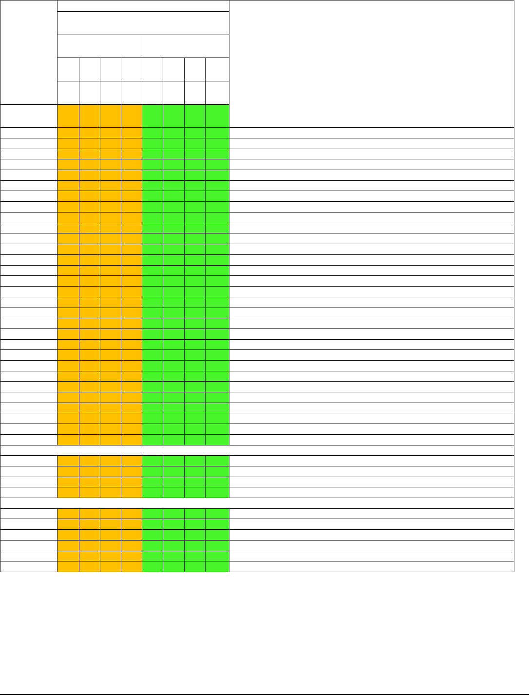
Appendix D: POST Code Diagnostic LED Decoder Intel® Server Board S2600GZ/GL TPS
Checkpoint
Diagnostic LED Decoder
Description
1 = LED On, 0 = LED Off
Upper Nibble
Lower Nibble
MSB
LSB
8h
4h
2h
1h
8h
4h
2h
1h
LED #
#7
#6
#5
#4
#3
#2
#1
#0
97h
1
0
0
1
0
1
1
1
DXE CON_OUT connect
98h
1
0
0
1
1
0
0
0
DXE CON_IN connect
99h
1
0
0
1
1
0
0
1
DXE SIO Init
9Ah
1
0
0
1
1
0
1
0
DXE USB start
9Bh
1
0
0
1
1
0
1
1
DXE USB reset
9Ch
1
0
0
1
1
1
0
0
DXE USB detect
9Dh
1
0
0
1
1
1
0
1
DXE USB enable
A1h
1
0
1
0
0
0
0
1
DXE IDE begin
A2h
1
0
1
0
0
0
1
0
DXE IDE reset
A3h
1
0
1
0
0
0
1
1
DXE IDE detect
A4h
1
0
1
0
0
1
0
0
DXE IDE enable
A5h
1
0
1
0
0
1
0
1
DXE SCSI begin
A6h
1
0
1
0
0
1
1
0
DXE SCSI reset
A7h
1
0
1
0
0
1
1
1
DXE SCSI detect
A8h
1
0
1
0
1
0
0
0
DXE SCSI enable
A9h
1
0
1
0
1
0
0
1
DXE verifying SETUP password
ABh
1
0
1
0
1
0
1
1
DXE SETUP start
ACh
1
0
1
0
1
1
0
0
DXE SETUP input wait
ADh
1
0
1
0
1
1
0
1
DXE Ready to Boot
AEh
1
0
1
0
1
1
1
0
DXE Legacy Boot
AFh
1
0
1
0
1
1
1
1
DXE Exit Boot Services
B0h
1
0
1
1
0
0
0
0
RT Set Virtual Address Map Begin
B1h
1
0
1
1
0
0
0
1
RT Set Virtual Address Map End
B2h
1
0
1
1
0
0
1
0
DXE Legacy Option ROM init
B3h
1
0
1
1
0
0
1
1
DXE Reset system
B4h
1
0
1
1
0
1
0
0
DXE USB Hot plug
B5h
1
0
1
1
0
1
0
1
DXE PCI BUS Hot plug
B6h
1
0
1
1
0
1
1
0
DXE NVRAM cleanup
B7h
1
0
1
1
0
1
1
1
DXE Configuration Reset
00h
0
0
0
0
0
0
0
0
INT19
S3 Resume
E0h
1
1
1
0
0
0
0
0
S3 Resume PEIM (S3 started)
E1h
1
1
1
0
0
0
0
1
S3 Resume PEIM (S3 boot script)
E2h
1
1
1
0
0
0
1
0
S3 Resume PEIM (S3 Video Repost)
E3h
1
1
1
0
0
0
1
1
S3 Resume PEIM (S3 OS wake)
BIOS Recovery
F0h
1
1
1
1
0
0
0
0
PEIM which detected forced Recovery condition
F1h
1
1
1
1
0
0
0
1
PEIM which detected User Recovery condition
F2h
1
1
1
1
0
0
1
0
Recovery PEIM (Recovery started)
F3h
1
1
1
1
0
0
1
1
Recovery PEIM (Capsule found)
F4h
1
1
1
1
0
1
0
0
Recovery PEIM (Capsule loaded)
POST Memory Initialization MRC Diagnostic Codes
There are two types of POST Diagnostic Codes displayed by the MRC during memory initialization; Progress
Codes and Fatal Error Codes.
The MRC Progress Codes are displays to the Diagnostic LEDs that show the execution point in the MRC
operational path at each step.
Revision 2.4
214