
S2600GZ and S2600GL
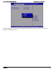
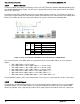
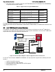


Table Of Contents
- 1. Introduction
- 2. Product Overview
- 3. Product Architecture Overview
- 3.1 Processor Support
- 3.2 Processor Functions Overview
- 3.2.1 Processor Core Features:
- 3.2.2 Supported Technologies:
- 3.2.3 Intel® QuickPath Interconnect
- 3.2.4 Integrated Memory Controller (IMC) and Memory Subsystem
- 3.2.4.1 Supported Memory
- 3.2.4.2 Memory Slot Identification and Population Rules
- 3.2.4.3 Publishing System Memory
- 3.2.4.4 Integrated Memory Controller Operating Modes
- 3.2.4.5 Memory RAS Support
- 3.2.5 Processor Integrated I/O Module (IIO)
- 3.3 Intel® C602 Chipset Functional Overview
- 3.4 Integrated Baseboard Management Controller Overview
- 4. System Security
- 5. Technology Support
- 6. Platform Management Functional Overview
- 6.1 Baseboard Management Controller (BMC) Firmware Feature Support
- 6.2 Advanced Configuration and Power Interface (ACPI)
- 6.3 Power Control Sources
- 6.4 BMC Watchdog
- 6.5 Fault Resilient Booting (FRB)
- 6.6 Sensor Monitoring
- 6.7 Field Replaceable Unit (FRU) Inventory Device
- 6.8 System Event Log (SEL)
- 6.9 System Fan Management
- 6.10 Messaging Interfaces
- 6.10.1 User Model
- 6.10.2 IPMB Communication Interface
- 6.10.3 LAN Interface
- 6.10.4 Address Resolution Protocol (ARP)
- 6.10.5 Internet Control Message Protocol (ICMP)
- 6.10.6 Virtual Local Area Network (VLAN)
- 6.10.7 Secure Shell (SSH)
- 6.10.8 Serial-over-LAN (SOL 2.0)
- 6.10.9 Platform Event Filter (PEF)
- 6.10.10 LAN Alerting
- 6.10.11 Alert Policy Table
- 6.10.12 SM-CLP (SM-CLP Lite)
- 6.10.13 Embedded Web Server
- 6.10.14 Virtual Front Panel
- 6.10.15 Embedded Platform Debug
- 6.10.16 Data Center Management Interface (DCMI)
- 6.10.17 Lightweight Directory Authentication Protocol (LDAP)
- 7. Advanced Management Feature Support (RMM4)
- 8. On-board Connector/Header Overview
- 9. Reset and Recovery Jumpers
- 10. Light Guided Diagnostics
- 11. Power Supply Specification Guidelines
- 11.1 Power Supply DC Output Connector
- 11.2 Power Supply DC Output Specification
- 11.2.1 Output Power/Currents
- 11.2.2 Standby Output
- 11.2.3 Voltage Regulation
- 11.2.4 Dynamic Loading
- 11.2.5 Capacitive Loading
- 11.2.6 Grounding
- 11.2.7 Closed loop stability
- 11.2.8 Residual Voltage Immunity in Standby mode
- 11.2.9 Common Mode Noise
- 11.2.10 Soft Starting
- 11.2.11 Zero Load Stability Requirements
- 11.2.12 Hot Swap Requirements
- 11.2.13 Forced Load Sharing
- 11.2.14 Ripple/Noise
- 11.2.15 Timing Requirements
- 12. BIOS Setup Utility
- Table 60. BIOS Setup: Keyboard Command Bar
- Back to [Main Screen]
- Back to [Main Screen]
- Back to [Main Screen]
- Back to [Main Screen]
- Back to [Main Screen]
- Back to [Main Screen]
- Back to [Main Screen]
- Back to [Main Screen]
- Back to [Advanced Screen]
- Back to [Advanced Screen]
- Back to [Advanced Screen]
- Back to [Advanced Screen]
- Back to [Advanced Screen]
- Back to [Advanced Screen]
- Back to [Advanced Screen]
- Back to [Advanced Screen]
- Screen Field Descriptions:
- Back to [Processor Configuration Screen] — [Advanced Screen]
- Back to [Processor Configuration Screen] — [Advanced Screen]
- Back to [Processor Configuration Screen] — [Advanced Screen]
- Back to [Processor Configuration Screen] — [Advanced Screen]
- Back to [Processor Configuration Screen] — [Advanced Screen]
- Back to [Processor Configuration Screen] — [Advanced Screen]
- Back to [Processor Configuration Screen] — [Advanced Screen]
- Back to [Processor Configuration Screen] — [Advanced Screen]
- Back to [Processor Configuration Screen] — [Advanced Screen]
- Back to [Processor Configuration Screen] — [Advanced Screen]
- Back to [Processor Configuration Screen] — [Advanced Screen]
- Back to [Processor Configuration Screen] — [Advanced Screen]
- Back to [Processor Configuration Screen] — [Advanced Screen]
- Back to [Processor Configuration Screen] — [Advanced Screen]
- Back to [Processor Configuration Screen] — [Advanced Screen]
- Back to [Processor Configuration Screen] — [Advanced Screen]
- Back to [Processor Configuration Screen] — [Advanced Screen]
- Back to [Processor Configuration Screen] — [Advanced Screen]
- Back to [Processor Configuration Screen] — [Advanced Screen]
- Back to [Processor Configuration Screen] — [Advanced Screen]
- Back to [Processor Configuration Screen] — [Advanced Screen]
- Back to [Processor Configuration Screen] — [Advanced Screen]
- Back to [Processor Configuration Screen] — [Advanced Screen]
- Back to [Processor Configuration Screen] — [Advanced Screen]
- Back to [Processor Configuration Screen] — [Advanced Screen]
- Back to [Processor Configuration Screen] — [Advanced Screen]
- Back to [Processor Configuration Screen] — [Advanced Screen]
- Back to Processor Configuration Screen] — [Advanced Screen]
- Back to [Processor Configuration Screen] — [Advanced Screen]
- Back to [Processor Configuration Screen] — [Advanced Screen]
- Back to [Processor Configuration Screen] — [Advanced Screen]
- Back to [Processor Configuration Screen] — [Advanced Screen]
- Back to [Processor Configuration Screen] — [Advanced Screen]
- Figure 44. Power & Performance Screen
- Back to [Power & Performance Screen] — [Advanced Screen]
- Figure 45. Memory Configuration Screen
- Back to [Memory Configuration Screen] — [Advanced Screen]
- Back to [Memory Configuration Screen] — [Advanced Screen]
- Back to [Memory Configuration Screen] — [Advanced Screen]
- Back to [Memory Configuration Screen] — [Advanced Screen]
- Back to [Memory Configuration Screen] — [Advanced Screen]
- Back to [Memory Configuration Screen] — [Advanced Screen]
- Back to [Memory Configuration Screen] — [Advanced Screen]
- Back to [Memory Configuration Screen] — [Advanced Screen]
- Back to [Memory Configuration Screen] — [Advanced Screen]
- Back to [Memory Configuration Screen] — [Advanced Screen]
- Back to [Memory Configuration Screen] — [Advanced Screen]
- Back to [Memory Configuration Screen] — [Advanced Screen]
- Back to [Memory Configuration Screen] — [Advanced Screen]
- Figure 46. Memory RAS and Performance Configuration Screen
- Figure 47. Mass Storage Controller Configuration Screen
- Screen Field Descriptions:
- One of these strings:
- Back to [Mass Storage Controller Configuration Screen]
- One of these strings:
- Back to [Mass Storage Controller Configuration Screen]
- Back to [Mass Storage Controller Configuration Screen]
- Back to [Mass Storage Controller Configuration Screen]
- Back to [Mass Storage Controller Configuration Screen]
- Back to [Mass Storage Controller Configuration Screen]
- Back to [Mass Storage Controller Configuration Screen]
- Back to [Mass Storage Controller Configuration Screen]
- Names of Storage Modules supported at this time are:
- Back to [Mass Storage Controller Configuration Screen]
- Back to [Mass Storage Controller Configuration Screen]
- Figure 48. PCI Configuration Screen
- Back to [PCI Configuration Screen] — [Advanced Screen]
- Back to [PCI Configuration Screen] — [Advanced Screen]
- Back to [PCI Configuration Screen] — [Advanced Screen]
- Back to [PCI Configuration Screen] — [Advanced Screen]
- Back to [PCI Configuration Screen] — [Advanced Screen]
- Back to [PCI Configuration Screen] — [Advanced Screen]
- Back to [PCI Configuration Screen] — [Advanced Screen]
- Figure 49. NIC Configuration Screen
- One of these strings:
- One of these strings:
- Figure 50. Serial Port Configuration Screen
- Back to [Serial Port Configuration Screen]
- Back to [Serial Port Configuration Screen]
- Back to [Serial Port Configuration Screen]
- Back to [Serial Port Configuration Screen]
- Back to [Serial Port Configuration Screen]
- Back to [Serial Port Configuration Screen]
- Figure 51. USB Configuration Screen
- Back to [USB Configuration Screen]
- Back to [USB Configuration Screen]
- Back to [USB Configuration Screen]
- Back to [USB Configuration Screen]
- Back to [USB Configuration Screen]
- Back to [USB Configuration Screen]
- Back to [USB Configuration Screen]
- Figure 52. System Acoustic and Performance Configuration
- Back to [System Acoustic and Performance Configuration]
- Back to [System Acoustic and Performance Configuration]
- Back to [System Acoustic and Performance Configuration]
- Back to [System Acoustic and Performance Configuration]
- Back to [System Acoustic and Performance Configuration]
- Figure 53. Security Screen
- Back to [Security Screen]
- Back to [Security Screen]
- Back to [Security Screen]
- Back to [Security Screen]
- Back to [Security Screen]
- Back to [Security Screen]
- Back to [Security Screen]
- Back to [Security Screen]
- Figure 54. Server Management Screen
- Back to [Server Management Screen]
- Back to [Server Management Screen]
- Back to [Server Management Screen]
- Back to [Server Management Screen]
- Back to [Server Management Screen]
- Back to [Server Management Screen]
- Back to [Server Management Screen]
- Back to [Server Management Screen]
- Back to [Server Management Screen]
- Back to [Server Management Screen]
- Back to [Server Management Screen]
- Back to [Server Management Screen]
- Back to [Server Management Screen]
- Back to [Server Management Screen]
- Back to [Server Management Screen]
- Back to [Server Management Screen]
- Back to [Server Management Screen]
- Back to [Server Management Screen]
- Back to [Server Management Screen]
- Back to [Server Management Screen]
- Figure 55. Console Redirection Screen
- Back to [Console Redirection Screen] — [Server Management Screen]
- Back to [Console Redirection Screen] — [Server Management Screen]
- Back to [Console Redirection Screen] — [Server Management Screen]
- Back to [Console Redirection Screen] — [Server Management Screen]
- Back to [Console Redirection Screen] — [Server Management Screen]
- Back to [Console Redirection Screen] — [Server Management Screen]
- Figure 56. System Information Screen
- Back to [System Information Screen] — [Server Management Screen]
- Back to [System Information Screen] — [Server Management Screen]
- Back to [System Information Screen] — [Server Management Screen]
- Back to [System Information Screen] — [Server Management Screen]
- Back to [System Information Screen] — [Server Management Screen]
- Back to [System Information Screen] — [Server Management Screen]
- Back to [System Information Screen] — [Server Management Screen]
- Back to [System Information Screen] — [Server Management Screen]
- Back to [System Information Screen] — [Server Management Screen]
- Back to [System Information Screen] — [Server Management Screen]
- Back to [System Information Screen] — [Server Management Screen]
- Figure 57. BMC LAN Configuration Screen
- Back to [BMC LAN Configuration Screen] — [Server Management Screen]
- Option Values: [Entry Field 0.0.0.0, 0.0.0.0 is default]
- Back to [BMC LAN Configuration Screen] — [Server Management Screen]
- Option Values: [Entry Field 0.0.0.0, 0.0.0.0 is default]
- Back to [BMC LAN Configuration Screen] — [Server Management Screen]
- Option Values: [Entry Field 0.0.0.0, 0.0.0.0 is default]
- Back to [BMC LAN Configuration Screen] — [Server Management Screen]
- Back to [BMC LAN Configuration Screen] — [Server Management Screen]
- Back to [BMC LAN Configuration Screen] — [Server Management Screen]
- Back to [BMC LAN Configuration Screen] — [Server Management Screen]
- Back to [BMC LAN Configuration Screen] — [Server Management Screen]
- Back to [BMC LAN Configuration Screen] — [Server Management Screen]
- Back to [BMC LAN Configuration Screen] — [Server Management Screen]
- Back to [BMC LAN Configuration Screen] — [Server Management Screen]
- Option Values: [Entry Field 0.0.0.0, 0.0.0.0 is default]
- Back to [BMC LAN Configuration Screen] — [Server Management Screen]
- Option Values: [Entry Field 0.0.0.0, 0.0.0.0 is default]
- Back to [BMC LAN Configuration Screen] — [Server Management Screen]
- Option Values: [Entry Field 0.0.0.0, 0.0.0.0 is default]
- Back to [BMC LAN Configuration Screen] — [Server Management Screen]
- Back to [BMC LAN Configuration Screen] — [Server Management Screen]
- Back to [BMC LAN Configuration Screen] — [Server Management Screen]
- Back to [BMC LAN Configuration Screen] — [Server Management Screen]
- Back to [BMC LAN Configuration Screen] — [Server Management Screen]
- Back to [BMC LAN Configuration Screen] — [Server Management Screen]
- Back to [BMC LAN Configuration Screen] — [Server Management Screen]
- Back to [BMC LAN Configuration Screen] — [Server Management Screen]
- Back to [BMC LAN Configuration Screen] — [Server Management Screen]
- Back to [BMC LAN Configuration Screen] — [Server Management Screen]
- Back to [BMC LAN Configuration Screen] — [Server Management Screen]
- Figure 58. Boot Options Screen
- Back to [Boot Options Screen]
- Back to [Boot Options Screen]
- Back to [Boot Options Screen]
- Back to [Boot Options Screen]
- Back to [Boot Options Screen]
- Back to [Boot Options Screen]
- Back to [Boot Options Screen]
- Back to [Boot Options Screen]
- Back to [Boot Options Screen]
- Back to [Boot Options Screen]
- Back to [Boot Options Screen]
- Back to [Boot Options Screen]
- Back to [Boot Options Screen]
- Back to [Boot Options Screen]
- Back to [Boot Options Screen]
- Back to [Boot Options Screen]
- Figure 59. CDROM Order Screen
- Back to [CDROM Order Screen] — [Boot Options Screen]
- Figure 60. Hard Disk Order Screen
- Back to [Hard Disk Order Screen] — [Boot Options Screen]
- Figure 61. Floppy Order Screen
- Back to [Floppy Order Screen] — [Boot Options Screen]
- Figure 62. Network Device Order Screen
- Back to [Network Device Order Screen] — [Boot Options Screen]
- Figure 63. BEV Device Order Screen
- Back to [BEV Device Order Screen] — [Boot Options Screen]
- Figure 64. Add EFI Boot Option Screen
- Figure 65. Delete EFI Boot Option Screen
- Figure 66. Boot Manager Screen
- Back to [Boot Manager Screen]
- Back to [Boot Manager Screen]
- Figure 67. Error Manager Screen
- Back to [Error Manager Screen]
- Back to [Error Manager Screen]
- Back to [Error Manager Screen]
- Back to [Error Manager Screen]
- Figure 68. Save & Exit Screen
- Back to [Save & Exit Screen]
- Back to [Save & Exit Screen]
- Back to [Save & Exit Screen]
- Back to [Save & Exit Screen]
- Back to [Save & Exit Screen]
- Back to [Save & Exit Screen]
- Back to [Save & Exit Screen]
- Appendix A: Integration and Usage Tips
- Appendix B: Integrated BMC Sensor Tables
- Appendix C: Management Engine Generated SEL Event Messages
- Appendix D: POST Code Diagnostic LED Decoder
- Appendix E: POST Code Errors
- Appendix F: Supported Intel® Server Systems
Product Architecture Overview Intel® Server Board S2600GZ/GL TPS
3.4.1
Super I/O Controller
The integrated super I/O controller provides support for the following features as implemented on the server
board:
Two Fully Functional Serial Ports, compatible with the 16C550
Serial IRQ Support
Up to 16 Shared direct GPIO’s
Serial GPIO support for 80 general purpose inputs and 80 general purpose outputs available for host
processor
Programmable Wake-up Event Support
Plug and Play Register Set
Power Supply Control
Host SPI bridge for system BIOS support
3.4.1.1
Keyboard and Mouse Support
The server board does not support PS/2 interface keyboards and mice. However, the system BIOS recognizes
USB specification-compliant keyboard and mice.
3.4.1.2
Wake-up Control
The super I/O contains functionality that allows various events to power on and power off the system.
3.4.2
Graphics Controller and Video Support
The integrated graphics controller provides support for the following features as implemented on the server
board:
Integrated Graphics Core with 2D Hardware accelerator
DDR-3 memory interface with 16 MB of memory allocated and reported for graphics memory
High speed Integrated 24-bit RAMDAC
Single lane PCI-Express host interface running at Gen 1 speed
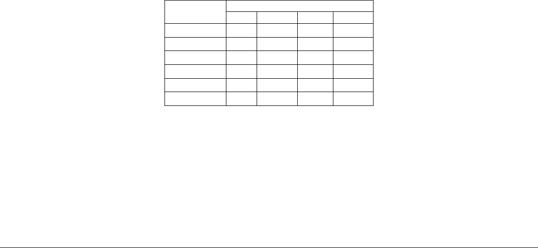
The integrated video controller supports all standard IBM VGA modes. The following table shows the 2D
modes supported for both CRT and LCD:
Table 17. Video Modes
2D Mode
2D Video Mode Support
8 bpp
16 bpp
24 bpp
32 bpp
640x480
X
X
X
X
800x600
X
X
X
X
1024x768
X
X
X
X
1152x864
X
X
X
X
1280x1024
X
X
X
X
1600x1200**
X
X
** Video resolutions at 1600x1200 and higher are only supported through the external video
connector located on the rear I/O section of the server board. Utilizing the optional front panel
video connector may result in lower video resolutions.
The server board provides two video interfaces. The primary video interface is accessed using a standard 15-
pin VGA connector found on the back edge of the server board. In addition, video signals are routed to a 14-
pin header labeled “FP_Video” on the leading edge of the server board, allowing for the option of cabling to a
front panel video connector. Attaching a monitor to the front panel video connector will disable the primary
external video connector on the back edge of the board.
The BIOS supports dual-video mode when an add-in video card is installed.
Revision 2.4
46