
Technical Product Specification

Intel® Local Control Panel for EPSD Platforms TPS Firmware Functional Specification
Revision 1.0 Intel order number G83726-001
7
3. Firmware Functional Specification
3.1 Overview
LCD (Local Control Display) is a one line character display that resides on the front panel of a
chassis. It can display maximum of 16 characters at a time. However, a few special characters
such as {, }, `, ~, and ^ are not available in the current LCD controller supported set of
characters. So these characters are mapped to their nearest lookalike characters of LCD. This
device also contains three buttons (Left, Right, and Enter). The user can select the contents that
need to be displayed on the LCD screen by operating these buttons. The BMC firmware drives
the display of this LCD panel based on the user’s selection. These three buttons are connected
to the GPIO pins of the BMC and the LCD controller is connected to the BMC using I
2
C bus.
3.2 LCD Functionality
The LCD device provides the following features:
Displays a banner when the system is healthy. The default banner is the Server Name.
One exception is when a user sets a custom string using the command, “Write LCD
Custom String (0xB3)”, the set custom string will become the banner automatically, until
the user changes the banner option in the banner configuration menu.
Displays active error messages when the system is not healthy.
Provides the ability to quickly see asset information on system without having to open
the chassis.
Provides basic server management configuration.
The LCD display is menu driven. Based on the user’s selection, respective menu items are
displayed. As soon as the system gets power, the LCD panel shall try to display the fault
detected in the system. If more than one fault exists, it displays the latest high severity fault
(event). If there are no faults, a banner is displayed. Default banner is Server Name. Server
Name is the value specified as the product name in the product FRU information in the main
board BMC FRU. User can set any of the parameters given under the banner configuration
menu as a banner string, which will be discussed later in this section. When the system’s status
is degraded, the corresponding active event will be displayed in place of the banner. During an
error, background color will be light amber in color. The LCD panel returns to a light green or
blue background when there are no longer any degraded, non-fatal, or fatal events active. The
LCD panel shall operate in lock-step with the system status LED. For example, if the system is
operating normally and an event occurs that results in the system status LED to blink green,
then the LCD shall display the degraded event that triggered the systems status LED to blink.
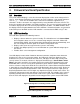
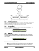
Figure 8: Background color during normal scenario
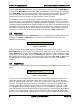
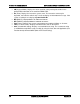
Figure 9: Background color during error
<Banner>
<Error>