
Technical Product Specification

Intel® Local Control Panel for EPSD Platforms TPS Installing and Removing the Intel® Local Control Panel
Revision 1.0 Intel order number G83726-001
19
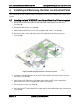
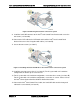
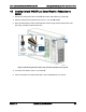
Figure 30: Removing the bracket in a 2U server system
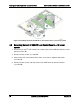
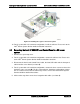
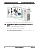
9. Install the front USB connecter to the Intel
®
Local Control Panel bracket and secure the
two screws (see letter G).
10. Connect the LCP cable to the LCP board and install the Intel
®
Local Control Panel
bracket into server chassis together with cables (see letter H).
11. Secure the two screws (see letter I).
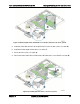
Figure 31: Installing the Intel
®
A1U2ULCP Local Control Panel in a 2U server system
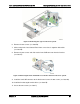
12. Install the cage into server chassis (see letter J). For 2U system with 3.5” hard drive
configuration, install the clip to server chassis.
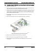
13. For 2U system with 2.5” hard drive configuration, secure the three screws (see letter K).
For 2U system with 3.5” hard drive configuration, secure the six screws. Please refer to
the Intel
®
Server System Service Guide for detailed instructions.
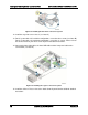
14. Connect the Intel
®
Local Control Panel cable, the front USB cable and the front panel
cable to the server board (see letter L).