
Technical Product Specification

List of Figures Intel® Local Control Panel for EPSD Platforms TPS
Intel order number G83726-001 Revision 1.0
iv
List of Figures
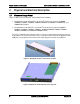
Figure 1: A1U2ULCP for Intel
®
Rack Server Systems ................................................................. 2
Figure 2: A4ULCP for Intel
®
Pedestal Server Systems ................................................................ 2
Figure 3: Mounting the A1U2ULCP in an Intel
®
2U Server Chassis ............................................. 3
Figure 4: Mounting the A1U2ULCP in an Intel
®
1U Server Chassis ............................................. 3
Figure 5: Mounting the A4ULCP in an Intel
®
Pedestal Server Chassis ........................................ 3
Figure 6: Intel
®
A1U2ULCP Local Control Panel ......................................................................... 4
Figure 7: Intel
®
A4ULCP Local Control Panel .............................................................................. 5
Figure 8: Background color during normal scenario .................................................................... 7
Figure 9: Background color during error ...................................................................................... 7
Figure 10: Main Menu ................................................................................................................. 8
Figure 11: Event Menu ................................................................................................................ 8
Figure 12: View Menu ................................................................................................................. 9
Figure 13: System Firmware Versions Menu ............................................................................... 9
Figure 14: System Information menu ........................................................................................ 10
Figure 15: BMC LAN Configuration ........................................................................................... 10
Figure 16: Power Consumed by the System Currently .............................................................. 11
Figure 17: Last BIOS POST Code............................................................................................. 11
Figure 18: Configure Menu Items .............................................................................................. 11
Figure 19: BMC IP Configuration Menu ..................................................................................... 11
Figure 20: BMC IP Source Configuration Menu......................................................................... 11
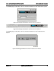
Figure 21: Screen shot for Configuring IP Address, Subnet Mask, and Gateway ...................... 12
Figure 22: State transition diagram for setting IP Address ......................................................... 13
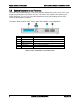
Figure 23: Boot options configuration menu .............................................................................. 13
Figure 24: Banner configuration menu ...................................................................................... 13
Figure 25: Removing the bracket in a 1U server system ........................................................... 15
Figure 26: Installing the Intel
®
A1U2ULCP Local Control Panel in a 1U server system ............. 16
Figure 27: Removing the Intel
®
A1U2ULCP Local Control Panel in a 1U server system ........... 17
Figure 28: Installing the bracket in a 1U server system ............................................................. 17
Figure 29: Removing the cage in a 2U server system ............................................................... 18
Figure 30: Removing the bracket in a 2U server system ........................................................... 19
Figure 31: Installing the Intel
®
A1U2ULCP Local Control Panel in a 2U server system ............. 19
Figure 32: Installing the cage in a 2U server system ................................................................. 20
Figure 33: Removing the cage in a 2U server system ............................................................... 21
Figure 34: Removing the Intel
®
A1U2ULCP Local Control Panel in a 2U server system ........... 21