
Quick Installation Guide Part 2


8
General Installation Process
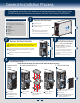
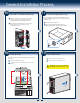
Install Hard Drive ... Continued
Install 2.5" Hard Drive into 3.5" Hot-swap Hard Drive Carrier as option:
d4
d2
d3
Install the HDD interface bracket from
top. Secure the bracket with three
screws as shown.
Slide the 2.5" HDD into the bracket to
align the screw holes with the right and
left rail.
Secure the hard disk drive using
the four screws for 2.5" HDD.
TOP
BREAK OFF TAB
BEFORE MOUTING
2.5´´ HARD DRIVE
d2
2.5" HDD
d3
d4
2.5" HDD
d1
Break off the tab on the
HDD interface bracket.
d1
Bottom
View
5
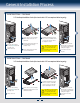
Install Tool-less CD-ROM or DVD-ROM Drive
C
Attach slides to the DVD or CD-ROM drive
by pressing the slides firmly into the side
dimples on the DVD or CD-ROM drive.
B
Get the slides from the
chassis side.
D
Insert the drive/slide assembly
into the device bay until the
slides lock into place.
A
Press the release latch and use
the finger holes to Pull out the
EMI shield.
Finger Holes
A
D
B
C
6
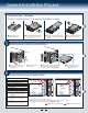
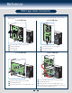
Install and Route Data and Power Cables
RED indicates power cable routing BLUE indicates data cable routing
Note:
Front Panel, USB cable are pre-routed by the factory.
SATA adapter cables are needed in order to connect power cable to fixed SATA HDD connector.
See more backplane cable connection instruction in Reference in P14
A. CPU1/CPU2 Power Cable
B. Server Board Main Power Cable
C. Power Cable to Hard Drive Bay
D. Power Cable to ODD
E. Front Panel Cable, USB Cable
F. ODD Data Cable
G. SATA cable and SGPIO** cable
H. PMBus* Cable
I. HSBP_I
2
C** Cable (5pin to 3pin, provide
connection from hot-swap back plane to
server board)
J. HSBP_I
2
C Cable (5pin to 5pin, only for
the chassis with 2 hot-swap back plane
cascade)
Description
**only for the chassis with hot-swap drive bay
*only for the chassis with hot-swap power supply
Server Board
Power Supply
CPU2 CPU1
Main Power
Front
Panel
SAS/SATA
SGPIO**
HSBP_I
2
C**
USB
B
A
D
C
H
I
J
G
E
F
PMBus*
Server Board
Power Supply
CPU1
Front
Panel
SAS/SATA
SGPIO**
HSBP_I
2
C**
USB
D
C
I
J
G
E
F
CPU2
Main Power
B
A
PMBus*
H