
Technical product specification

Intel® Server Board S2600CP Connector/Header Locations and Pin-outs
Intel
®
Server Board S2600CP and Server System P4000CP TPS
Revision 1.8
Intel order number G26942-005
92
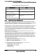
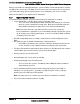
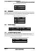
Table 31. Local Front Panel Connector Pin-out
Pin
Signal Name
Pin
Signal Name
1
SMB_SENSOR_3V3STBY_DATA
2
GND
3
SMB_SENSOR_3V3STBY_CLK
4
P3V3_AUX
5
FM_LCP_ENTER_N
6
FM_LCP_LEFT_N
7
FM_LCP_RIGHT_N
7.3 On Board Storage Connectors
The server board provides connectors for support of several storage device options. This
section provides a functional overview and pin-out of each connector.
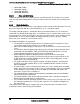
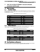
7.3.1 SATA Connectors: 6Gbps
The server board includes two white single port SATA only connectors capable of transfer rates
of up to 6Gb/s. The following table provides the pin-out for both connectors.
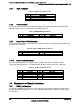
Table 32. SATA 6Gbps Connector Pin-out
Pin
Signal Name
1
GND
2
SATA_TX_P
3
SATA_TX_N
4
GND
5
SATA_RX_N
6
SATA_RX_P
7
GND
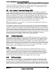
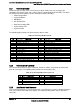
7.3.2 SATA Connectors: 3Gbps
The server board includes four black single port SATA only connectors capable of transfer rates
of up to 3Gbps. The following table provides the pin-out for both connectors.
Table 33. SATA 3Gbps Connector Pin-out
Pin
Signal Name
1
GND
2
SATA_TX_P
3
SATA_TX_N
4
GND
5
SATA_RX_N
6
SATA_RX_P
7
GND
7.3.3 SATA SGPIO Connector
SGPIO uses a 5pin header. This is to incorporate a ground conductor as an SI improvement
over previous generation products. Based on measurement data, add the ground indication is
strongly recommended. The 5pin connector will be consistent with other HSBPs, in this way
cable commonality is improved.