
Technical product specification

Intel®
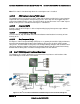
Server Board S2600CP Functional Architecture Intel
®
Server Board S2600CP and Server System P4000CP TPS
Revision 1.8
Intel order number G26942-005
38
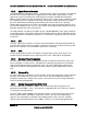
4.2.2.4.1 Independent Channel Mode
Channels can be populated in any order in Independent Channel Mode. All four channels may
be populated in any order and have no matching requirements. All channels must run at the
same interface frequency but individual channels may run at different DIMM timings (RAS
latency, CAS Latency, and so forth).
4.2.2.4.2 Rank Sparing Mode
In Rank Sparing Mode, one rank is a spare of the other ranks on the same channel. The spare
rank is held in reserve and is not available as system memory. The spare rank must have
identical or larger memory capacity than all the other ranks (sparing source ranks) on the same
channel. After sparing, the sparing source rank will be lost.
4.2.2.4.3 Mirrored Channel Mode
In Mirrored Channel Mode, the memory contents are mirrored between Channel 0 and Channel 2
and also between Channel 1 and Channel 3. As a result of the mirroring, the total physical
memory available to the system is half of what is populated. Mirrored Channel Mode requires
that Channel 0 and Channel 2, and Channel 1 and Channel 3 must be populated identically with
regards to size and organization. DIMM slot populations within a channel do not have to be
identical but the same DIMM slot location across Channel 0 and Channel 2 and across Channel
1 and Channel 3 must be populated the same.
4.2.2.4.4 Lockstep Channel Mode
In Lockstep Channel Mode, each memory access is a 128-bit data access that spans Channel 0
and Channel 1, and Channel 2 and Channel 3. Lockstep Channel mode is the only RAS mode
that allows SDDC for x8 devices. Lockstep Channel Mode requires that Channel 0 and Channel
1, and Channel 2 and Channel 3 must be populated identically with regards to size and
organization. DIMM slot populations within a channel do not have to be identical but the same
DIMM slot location across Channel 0 and Channel 1 and across Channel 2 and Channel 3 must
be populated the same.
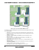
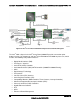
4.2.3 Processor Integrated I/O Module (IIO)
The processor’s integrated I/O module provides features traditionally supported through chipset
components. The integrated I/O module provides the following features:
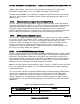
4.2.3.1.1 PCI Express* Interfaces
The integrated I/O module incorporates the PCI Express* interface and supports up to 40 lanes
of PCI Express. Intel
®
Server Board S2600CP supports six PCI-e slots from two processors:
From first processor:
o Slot 1: PCIe Gen III x4/x8 electrical with x8 physical connector
o Slot 2: PCIe Gen III x8 electrical with x8 physical connector
o Slot 3: PCIe Gen III x8 electrical with x8 open-ended physical connector
o Slot 4: PCIe Gen III x8 electrical with x8 physical connector
o Slot 6: PCIe Gen III x8 electrical with x16 connector, support riser card.
From second processor:
o Slot 5: PCIe Gen III x8 electrical with x8 open-ended physical connector