
Technical product specification

Intel
®
Server Board S2600CP and Server System P4000CP TPS Intel®
Server Board S2600CP Functional Architecture
Revision 1.8
Intel order number G26942-005
47
3.3 V
x8
16 GB/S
PCI Express*
Gen3
x8 PCI Express* Gen3 throughput
to Slot 6 (x16 mechanically)
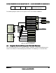
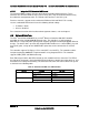
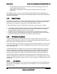
The following diagram shows the PCI layout for Intel
®
Server Board S2600CP4:
Slot 3 x8 Open Ended Conn
Slot 4 x8 Conn
Intel
®
Ethernet Controller
I350-AM4
Socket 1
PCIe Port 0/DMI2
PCIe Port 1a
PCIe Port 1b
PCIe Port 2a
PCIe Port 2b
PCIe Port 2c
PCIe Port 2d
PCIe Port 3a
PCIe Port 3b
PCIe Port 3c
PCIe Port 3d
Socket 2
PCIe Port 0/DMI2
PCIe Port 1a
PCIe Port 1b
PCIe Port 2a
PCIe Port 2b
PCIe Port 2c
PCIe Port 2d
PCIe Port 3a
PCIe Port 3b
PCIe Port 3c
PCIe Port 3d
SAS SCU 0
Virtual Root Port
B0,D17,F0
SATA
B0,D31,F2
EHCI1
B0,D29,F0
EHCI2
B0,D26,F0
Video
SATA Drives
USB Ports
SAS Drives
B0,D2,F0
B7,D0,F0-F3
B0,D1,F0
B0,D2,F2
B9,D0,F0
Slot 1 x8 Conn
Default
Slot 2 x8 Conn
B0,D3,F0
Slot 6 x16 Conn
Slot 5 x8 Open Ended Conn
B128,D2,F0
B0,D3,F2
PCIe Root Port 8
PCIe Root Port 1
B0,D28,F7
B0,D28,F0
B6,D0,F0
SMBus
B0,D31,F3
DMI to PCI Bridge
B0,D30,F0
HECI 2
B0,D22,F1
HECI 1
B0,D22,F0
Mux
ISA Bridge
B0,D31,F0
Figure 25. PCI Layout Diagram
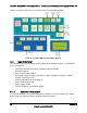
4.5 Integrated Baseboard Management Controller Overview
The server board utilizes the I/O controller, Graphics Controller, and Baseboard Management
features of the Emulex* Pilot-III Management Controller. The following is an overview of the