Intel® Server Board S5000VSA User’s Guide A Guide for Technically Qualified Assemblers of Intel® Identified Subassemblies/ Products Intel Order Number D36977-002
Disclaimer Information in this document is provided in connection with Intel® products. No license, express or implied, by estoppel or otherwise, to any intellectual property rights is granted by this document.
Safety Information Important Safety Instructions Read all caution and safety statements in this document before performing any of the instructions. See also Intel Server Boards and Server Chassis Safety Information on the Intel® Deployment Assistant and/or at http://support.intel.com/support/motherboards/ server/sb/cs-010770.htm. Wichtige Sicherheitshinweise Lesen Sie zunächst sämtliche Warnund Sicherheitshinweise in diesem Dokument, bevor Sie eine der Anweisungen ausführen.
重要安全指导 在执行任何指令之前,请阅读本文档中的所有注意事项及安全声明。 和/或 http://support.intel.com/support/motherboards/server/sb/CS-010770.
Warnings Heed safety instructions: Before working with your server product, whether you are using this guide or any other resource as a reference, pay close attention to the safety instructions. You must adhere to the assembly instructions in this guide to ensure and maintain compliance with existing product certifications and approvals. Use only the described, regulated components specified in this guide.
vi Intel® Server Board S5000VSA User’s Guide
Preface About this Manual Thank you for purchasing and using the Intel® Server Board S5000VSA. This manual is written for system technicians who are responsible for troubleshooting, upgrading, and repairing this server board. This document provides a brief overview of the features of the board/chassis, a list of accessories or other components you may need, troubleshooting information, and instructions on how to add and replace components on the Title of document.
Product Accessories This server board is compatible with the following Intel® Server Chassis: • Intel® Server Chassis SC5299DP • Intel® Server Chassis SC5299BRP You may need or want to purchase one or more of the following accessory items for your server: Processor, memory DIMMs, hard drive, CD-ROM or DVD-ROM drive, RAID controller, operating system.
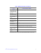
Table 1.
x Intel® Server Board S5000VSA User’s Guide
Contents Safety Information ..................................................................................................... iii Important Safety Instructions ................................................................................................ iii Wichtige Sicherheitshinweise ............................................................................................... iii Consignes de sécurité ................................................................................................
Installing and Removing Memory ........................................................................................ 17 Installing DIMMs .......................................................................................................... 17 Removing DIMMs ........................................................................................................ 19 Installing the Processor ...............................................................................................
Devices are not Recognized under Device Manager (Windows* Operating System) .44 Hard Drive(s) are not Recognized ...............................................................................44 Bootable CD-ROM Disk Is Not Detected .....................................................................45 LED Information ...........................................................................................................45 BIOS POST Beep Codes .............................................................
xiv Intel® Server Board S5000VSA User’s Guide
List of Tables Table 1. Additional Information and Software .........................................................................viii Table 2. Server Board Features ................................................................................................ 2 Table 3. NIC LED Descriptions .................................................................................................8 Table 4. Setup Menu Key Use .......................................................................................
xvi Intel® Server Board S5000VSA User’s Guide
List of Figures Figure 1. Intel® Server Board S5000VSA.................................................................................. 1 Figure 2. Server Board Connector and Component Locations ................................................. 6 Figure 3. Configuration Jumper Descriptions ............................................................................ 7 Figure 4. Back Panel Connectors.............................................................................................. 8 Figure 5.
xviii Intel® Server Board S5000VSA User’s Guide
1 Server Board Features This chapter briefly describes the main features of the Intel® Server Board S5000VSA. This chapter provides a photograph of the product, a list of the server board features, and diagrams showing the location of important components and connections on the server board. Figure 1.
Table 2 summarizes the features of the server board. Table 2.
RAID Support The Intel® Server Board S5000VSA is available in both SATA and SAS models. The SATA model has order code S5000VSASATA. The SAS model has order code S5000VSASAS. The SAS model provides both SAS and SATA support; the SATA model provides only SATA support. For information on configuring RAID, see the RAID Software Guide that is included on the Intel® Server Deployment Toolkit CD. SATA Server Board The Intel® Server Board S5000VSA provides an embedded SATA controller that supports both 1.5 and 3.
SAS Server Board In addition to the SATA features described above, SAS models of the server board (order code S5000VSASAS) also have a dual-mode 4-port Serial Attached SCSI (SAS) controller that supports both SAS and SATA hard disk drives. This controller is capable of data transfer rates of up to 3.0 Gbps per port.The SAS controller (in RAID mode) supports eight physical drives and eight logical arrays. The SAS controller (in native mode) supports up to 120 physical drives when expanders are used.
Connector and Component Locations A B C D E F UU TT G HI J K SS L RR M QQ PP N OO NN MM LL KK JJ II HH GG O P Q R EE CCAA X W FF DD BB Z Y VUT S AF000173 Intel® Server Board S5000VSA User’s Guide 5
A. PCI 32/33 Slot 1 B. PCIe* x4 Slot 3 C. PCI-X* 64/133 Slot 4 D. PCI-X 64/100 Slot 5 E. PCIe x4 Slot 6 F. Back Panel I/O Ports G. Diagnostic LEDs H. System ID LED I. System Status LED J. System Fan 6 K. System Fan 5 L. Main Power Connector M. Auxiliary Signal Connector N. DIMM Sockets O. Processor 1 Socket P. Processor 2 Socket Q. Processor Fan 2 Header R. Processor Fan 1 Header S. Processor Voltage Regulator T. Battery U. Processor Power Connector V.
Configuration Jumpers CMOS CLR 2 3 PASSWORD CLR Default Default 2 CLEAR CMOS 3 CLEAR PASSWORD J1J1 J1J2 AF000187 Jumper Name Jumper Purpose CMOS Clear If pins 2-3 are jumpered, the CMOS settings will be cleared on the next reset. These pins should be jumpered on 1-2 for normal operation. Password Clear If pins 2-3 are jumpered, administrator and user passwords will be cleared on the next reset. These pins should be jumpered on 1-2 for normal operation.
Back Panel Connectors A B H G C D F E AF000184 A. Mouse B. Serial Port B C. NIC 1 (10/100/1000 Mb) D. NIC 2 (10/100/1000 Mb) E. USB 2-3 F. USB 0-1 G. Video H. Keyboard Figure 4. Back Panel Connectors The NIC LEDs at the right and left of each NIC provide the following information. Table 3.
Hardware Requirements To avoid integration difficulties and possible board damage, your system must meet the requirements outlined below. For a list of qualified components, see the links under "Additional Information and Software." Processor One or two Dual-Core Intel®Xeon® processor 5000 sequence. For a complete list of supported processors, see the links under "Additional Information and Software." Memory The server board provides eight DIMM sockets across two channels, Channel A and Channel B.
In a mirrored system, the maximum usable memory is one-half of the installed memory, with a minimum of four DIMMs installed. Since the data is duplicated across DIMMs, it means that up to one-half of the installed DIMMs are actively in use at any one time. The remaining DIMMs are used for mirroring. Memory mirroring and memory sparing are mutually exclusive. Only one can be active at a time.
2 Server Utilities Using the BIOS Setup Utility This section describes the BIOS Setup Utility options, which is used to change server configuration defaults. You can run BIOS Setup with or without an operating system being present. See “Additional Information and Software” for a link to the Intel® S5000 Server Board Family Data Sheet where you will find details about specific BIOS setup screens.
“Setup Menu Key Use” describes the keyboard commands you can use in the BIOS Setup menus. Table 4. Setup Menu Key Use Key to Press Description Pressing on any menu invokes the general help window. Left and right arrows The left and right arrow keys are used to move between the major menu pages. The keys have no affect if a submenu or pick list is displayed. Up arrow Select Item up - The up arrow is used to select the previous value in a menu item's option list, or a value field pick list.
Table 4. Setup Menu Key Use Key to Press Description Save and Exit - Pressing causes the following message to appear: Setup Confirmation Save Configuration changes and exit now? [Yes] [No] If "Yes" is selected and the key is pressed, all changes are saved and Setup is exited. If "No" is selected and the key is pressed, or the key is pressed, the user is returned to where they were before was pressed without affecting any existing values.
Obtaining the Upgrade Download the BIOS image file to a temporary folder on your hard drive or a USB flash device. See “Additional Information and Software” for a link to the update software. Note: Review the instructions and release notes that are provided in the readme file distributed with the BIOS image file before attempting a BIOS upgrade. The release notes contain critical information regarding jumper settings, specific fixes, or other information to complete the upgrade.
Clearing the Password If the user or administrator password(s) is lost or forgotten, moving the password clear jumper into the "clear" position clears both passwords. The password clear jumper must be restored to its original position before a new password(s) can be set. 1. Power down the system and disconnect the AC power. 2. Open the server chassis. 3.
Clearing the CMOS If you are not able to access the BIOS setup screens, the CMOS Clear jumper will need to be used to reset the configuration RAM. 1. Power down the system and disconnect the AC power. 2. Open the server. 3. Move the jumper (J1J1) from the normal operation position, CMOS Clear by BMC, at pins 1 and 2 to the CMOS Clear Force Erase position, covering pins 2 and 3 as indicated in the following diagram.
3 Hardware Installations and Upgrades Before You Begin Before working with your server product, pay close attention to the “Safety Information” at the beginning of this manual.
DIMM A4 Socket DIMM A3 Socket DIMM A2 Socket DIMM A1 Socket DIMM B1 Socket DIMM B2 Socket DIMM B3 Socket DIMM B4 Socket C D B A AF000174 Figure 7. Installing Memory 6. Make sure the clips at either end of the DIMM socket(s) are pushed outward to the open position. 7. Holding the DIMM by the edges, remove it from its anti-static package. 8. Position the DIMM above the socket. Align the notch on the bottom edge of the DIMM with the key in the DIMM socket.
11. Replace the server's cover and reconnect the AC power cord. See the documentation that came with your server chassis for instructions on installing the server's cover. Removing DIMMs To remove a DIMM, follow these steps: 1. Observe the safety and ESD precautions in “Safety Information”. 2. Turn off all peripheral devices connected to the server. Turn off the server. 3. Remove the AC power cord from the server. 4. Remove the server's cover.
Installing the Processor To install a processor, follow these instructions: 1. Observe the safety and ESD precautions in “Safety Information”. 2. Turn off all peripheral devices connected to the server. Turn off the server. 3. Disconnect the AC power cord from the server. 4. Remove the server's cover. See the documentation that came with your server chassis for instructions on removing the server's cover. 5. Locate the processor socket and raise the socket handle completely (see Figure 8).
7. Take the processor out of the box and remove the protective shipping cover (see Figure 10). A AF000180 Figure 10. Removing the Shipping Cover 8. Orient the processor with the socket so that the processor cutouts match the socket notches. Install the processor as shown in Figure 11. A B AF000181 Figure 11. Installing the Processor Note: Make sure the alignment triangle mark and the alignment triangle cutout align correctly. 9. Remove the protective socket cover (see Figure 12).
Installing the Heat Sink(s) The heat sink has Thermal Interface Material (TIM) located on the bottom of it. Use caution when you unpack the heat sink so you do not damage the TIM. 1. Set the heat sink over the processor, lining up the four captive screws with the four posts surrounding the processor. 2. Loosely screw in the captive screws on the heat sink corners in a diagonal manner. Do no fully tighten one screw before tightening another. 3.
Removing a Processor 1. Observe the safety and ESD precautions in “Safety Information”. 2. Turn off all peripheral devices connected to the server. Turn off the server. 3. Remove the AC power cord from the server. 4. Remove the server's cover. See the documentation that came with your server chassis for instructions on removing the server's cover. 5. Unplug the processor fan cable from the server board. 6. Loosen the four captive screws on the corners of the heat sink. 7.
Replacing the Backup Battery The lithium battery on the server board powers the RTC for up to 10 years in the absence of power. When the battery starts to weaken, it loses voltage, and the server settings stored in CMOS RAM in the RTC (for example, the date and time) may be wrong. Contact your customer service representative or dealer for a list of approved devices. Warning: Danger of explosion if battery is incorrectly replaced.
1. Observe the safety and ESD precautions in “Safety Information”. 2. Turn off all peripheral devices connected to the server. Turn off the server. 3. Disconnect the AC power cord from the server. 4. Remove the server's cover and locate the battery. See the documentation that came with your server chassis for instructions on removing the server's cover. 5. Insert the tip of a small flat bladed screwdriver, or an equivalent, under the tab in the plastic retainer.
26 “Intel® Server Board S5000VSA User’s Guide”
Appendix A: Getting Help World Wide Web http://support.intel.com/support/motherboards/server/S5000VSA. Telephone All calls are billed US $25.00 per incident, levied in local currency at the applicable credit card exchange rate plus applicable taxes. (Intel reserves the right to change the pricing for telephone support at any time without notice). Before calling, fill out an “Intel® Server Issue Report Form”. A sample form is provided on the following pages.
In Asia-Pacific Region Australia.... 1800 649931 Cambodia.. 63 2 636 9797 (via Philippines) China ......... 800 820 1100 (toll-free) .................... 8 621 33104691 (not toll-free) Hong Kong 852 2 844 4456 India........... 0006517 2 68303634 (manual toll-free. You need an IDD-equipped telephone) Indonesia ... 803 65 7249 Korea ......... 822 767 2595 Malaysia .... 1 800 80 1390 Myanmar... 63 2 636 9796 (via Philippines) New Zealand 0800 444 365 Pakistan.....
Colombia ... Contact AT&T USA at 01 800 911 0010. Once connected, dial 800 843 4481 Costa Rica . Contact AT&T USA at 0 800 0 114 114. Once connected, dial 800 843 4481 Ecuador (Andimate) .... Contact AT&T USA at 1 999 119. Once connected, dial 800 843 4481 (Pacifictel) ..... Contact AT&T USA at 1 800 225 528. Once connected, dial 800 843 4481 Guatemala. Contact AT&T USA at 99 99 190. Once connected, dial 800 843 4481 Mexico ....... Contact AT&T USA at 001 800 462 628 4240.
30 Intel® Server Board S5000VSA User’s Guide
Appendix B: Regulatory and Compliance Information Product Regulatory Compliance Product Safety Compliance The Intel® Server Board S5000VSA complies with the following safety requirements: • • • • UL60950 - CSA 60950 (USA / Canada) EN60950 (Europe) IEC60950 (International) CB Certificate & Report, IEC60950 (report to include all country national deviations) • GOST R 50377-92 - Listed on one System License (Russia) • Belarus License - Listed on System License (Belarus) • CE - Low Voltage Directive 73/23/EE
• GOST R 50628-95 Immunity -Listed on one System License (Russia) • Belarus License - Listed on one System License (Belarus) • RRL MIC Notice No.
Table 5. Product Certification Markings Regulatory Compliance Region BSMI Marking (Class A) Taiwan RLL MIC Mark Korea Marking Electromagnetic Compatibility Notices FCC (USA) This device complies with Part 15 of the FCC Rules. Operation is subject to the following two conditions: (1) this device may not cause harmful interference, and (2) this device must accept any interference received, including interference that may cause undesired operation.
• Connect the equipment to an outlet on a circuit other than the one to which the receiver is connected. • Consult the dealer or an experienced radio/TV technician for help. Any changes or modifications not expressly approved by the grantee of this device could void the user's authority to operate the equipment. The customer is responsible for ensuring compliance of the modified product. Only peripherals (computer input/output devices, terminals, printers, etc.
Korean Compliance (RRL) English translation of the notice above: 1. Type of Equipment (Model Name): On License and Product 2. Certification No.: On RRL certificate. Obtain certificate from local Intel representative 3. Name of Certification Recipient: Intel Corporation 4. Date of Manufacturer: Refer to date code on product 5.
Restriction of Hazardous Substances (RoHS) Compliance Intel has a system in place to restrict the use of banned substances in accordance with the European Directive 2002/95/EC. Compliance is based on declaration that materials banned in the RoHS Directive are either (1) below all applicable substance threshold limits or (2) an approved/pending RoHS exemption applies. Note: RoHS implementing details are not fully defined and may change. Threshold limits and banned substances are noted below.
Appendix C: Troubleshooting This chapter helps you identify and solve problems that might occur while you are using the system. For any issue, first ensure you are using the latest firmware and files. Firmware upgrades include updates for BIOS, the baseboard management controller (BMC), and the hot-swap controller (HSC). See “Additional Information and Software” for a link to the software updates.
First Steps Checklist • Is AC power available at the wall outlet? • Are the power supplies plugged in? Check the AC cable(s) on the back of the chassis and at the AC source.
3. Make sure your video display monitor and keyboard are correctly connected to the system. Turn on the video monitor. Set its brightness and contrast controls to at least two thirds of their maximum ranges (see the documentation supplied with your video display monitor). 4. If the operating system normally loads from the hard disk drive, make sure there is no diskette in drive A and no CD-ROM disk in the CD-ROM drive. 5. If the power LED does light, attempt to boot from a CD-ROM disk. 6.
Try the solutions below in the order given. If you cannot correct the problem, contact your service representative or authorized dealer for help. Power Light Does Not Light Check the following: • Did you press the power-on button? • Is the system operating normally? If so, the power LED might be defective or the cable from the control panel to the server board might be loose.
• Make sure the memory DIMMs have been populated according to the system requirements. • Remove the memory DIMMs and re-seat them. • Make sure the processor(s) comply with the system requirements. • Make sure the processor(s) have been populated according to the system requirements. • Remove the processor(s) and re-seat them. If you are using an add-in video controller board, do the following: 1. Verify that the video works using the onboard video controller. 2.
• Are the fan power connectors properly connected to the server board? • Is the cable from the control panel board connected to the both the control panel board and to the server board? • Are the power supply cables properly connected to the server board? • Are there any shorted wires caused by pinched-cables or have power connector plugs been forced into power connector sockets the wrong way? CD-ROM Drive or DVD-ROM Drive Activity Light Does Not Light Check the following: • Are the CD-ROM/DVD-ROM drive'
Diagnostics pass but the connection fails • • • • • Make sure the network cable is securely attached. Make sure you specify the correct frame type in your NET.CFG file. The controller stopped working when an add-in adapter was installed. Make sure the cable is connected to the port from the onboard network controller. Make sure your BIOS is current. See “Additional Information and Software” for a link to the current version. • Make sure the other adapter supports shared interrupts.
• Use only an authorized copy. Unauthorized copies often do not work. • If you are running the software from a CD-ROM or DVD-ROM, try a different disk. • Make sure the correct device drivers installed. If the problems persist, contact the software vendor's customer service representative. Problems with Application Software that Ran Correctly Earlier Problems that occur after the system hardware and software have been running correctly sometimes indicate equipment failure.
• Make sure the drive is compatible. See “Additional Information and Software” for a link to the tested drives. • Make sure you have not exceeded the power budget for the server. See “Additional Information and Software” for a link to software to check your power budget. • If using SCSI drives, verify that each SCSI ID number is unique on the SCSI bus. See your drive documentation for details on setting the SCSI ID for your drives.
BIOS POST Beep Codes The table below lists the POST error beep codes. Prior to system video initialization, the BIOS uses these beep codes to inform users of error conditions. Please note that not all error conditions are supported by BIOS beep codes. Table 8. POST Error Beep Codes Number of Beeps 46 Reason for Beeps and Action to Take 1, 2, or 3 Memory error. Reseat the memory or replace the DIMMs with known good modules. 4 - 7 or 9 - 11 Fatal error indicating a possible serious system problem.
Appendix D: Intel® Server Issue Report Form Note: An on-line / automatic submission version of this form is available at http:// support.intel.com/support/motherboards/server/S5000SVA/. For the fastest service, please submit your form via the Internet.
DIMM Configuration DIMM A1 MB and Vendor / part number: __________________________________ DIMM A2 MB and Vendor / part number: __________________________________ DIMM A3 MB and Vendor / part number: __________________________________ DIMM A4 MB and Vendor / part number: __________________________________ DIMM B1 MB and Vendor / part number: __________________________________ DIMM B2 MB and Vendor / part number: __________________________________ DIMM B3 MB and Vendor / part number: ________________________
Peripheral Description Driver Revision IRQ I/O Base Address Make/Model Hot-swap or Fixed IRQ FW Revision FW Revision Add-in Video NIC On-Board NIC1 On-Board NIC2 Hard Drive Information Drive Type (SATA, SAS, etc) Management Information On-Board Platform Instrumentation only ___________________________________ Intel® System Management ______________________________________________ Control Panel Information Standard Control Panel _________________________________________________ Intel® Local Cont
Complete Problem Description In the space below, provide a complete description of the steps used to reproduce the problem or a complete description of where the problem can be found. Please also include any details on troubleshooting already done.