
Technical Product Specification
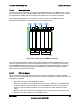

Table Of Contents
- 1. Introduction
- 2. Product Overview
- 3. Functional Architecture
- 3.1 Processor Support
- 3.1.1 Processor Population Rules
- 3.1.2 Multiple Processor Initialization
- 3.1.3 Enhanced Intel SpeedStep® Technology
- 3.1.4 Intel® Extended Memory 64 Technology (Intel® EM64T)
- 3.1.5 Execute Disable Bit Feature
- 3.1.6 Multi-Core Processor Support
- 3.1.7 Intel® Virtualization Technology
- 3.1.8 Platform Environmental Control Interface (PECI)
- 3.1.9 Common Enabling Kit (CEK) Design Support
- 3.2 Intel® 5400 Memory Controller Hub Chipset (Intel® 5400 MCH Chipset)
- 3.2.1 Processor Front-Side Buses
- 3.2.2 Snoop Filter
- 3.2.3 System Memory Controller and Memory Subsystem
- 3.2.3.1 Supported Memory
- 3.2.3.2 DIMM Population Rules and Supported DIMM Configurations
- 3.2.3.3 Minimum Memory Configuration
- 3.2.3.4 Memory upgrades
- 3.2.3.5 ECC Code Support
- 3.2.3.6 Memory Sparing
- 3.2.3.7 FBD Memory Thermal Management
- 3.2.3.8 BIOS Support of Memory Subsystem
- 3.2.3.9 Memory Error Handing
- 3.2.3.10 Memory Error Reporting
- 3.3 Intel® 6321ESB I/O Controller Hub
- 3.4 PCI Subsystem
- 3.4.1 Intel® 6321ESB I/O Controller Hub PCI32: 32-bit, 33-MHz PCI Bus Segment
- 3.4.2 Intel® 6321ESB I/O Controller Hub Port 1: x4 PCI Express* Bus Segment
- 3.4.3 Intel® 6321ESB I/O Controller Hub Port 2: x4 PCI Express* Bus Segment
- 3.4.4 MCH to Intel® 6321ESB I/O Controller Hub Chip-to-Chip Interface: Two x4 PCI Express* Bus Segments
- 3.4.5 MCH Ports 5-8: x16 Gen 2 PCI Express* Bus Segment
- 3.4.6 Scan Order
- 3.4.7 Resource Assignment
- 3.4.8 Automatic IRQ Assignment
- 3.4.9 Legacy Option ROM Support
- 3.4.10 EFI PCI APIs
- 3.4.11 Legacy PCI APIs
- 3.5 Video Support
- 3.6 Network Interface Controller (NIC)
- 3.7 Super I/O
- 3.1 Processor Support
- 4. Server Management
- 4.1 Intel® 6321ESB I/O Controller Hub Integrated Baseboard Management Controller (Integrated BMC) Feature Set
- 4.2 Advanced Configuration and Power Interface (ACPI)
- 4.3 System Initialization
- 4.4 Integrated Front Panel User Interface
- 4.5 Platform Control
- 4.6 Standard Fan Management
- 4.7 Private Management I2C Buses
- 4.8 Integrated BMC Messaging Interfaces
- 4.9 Event Filtering and Alerting
- 4.10 Watchdog Timer
- 4.11 System Event Log (SEL)
- 4.12 Sensor Data Record (SDR) Repository
- 4.13 Field Replaceable Unit (FRU) Inventory Device
- 4.14 Non-maskable Interrupt (NMI)
- 4.15 General Sensor Behavior
- 4.16 Processor Sensors
- 4.16.1 Processor Status Sensors
- 4.16.2 Processor VRD Over-temperature Sensor
- 4.16.3 ThermalTrip Monitoring
- 4.16.4 Internal Error (IERR) Monitoring
- 4.16.5 Dynamic Processor Voltage Monitoring
- 4.16.6 Processor Temperature Monitoring
- 4.16.7 Processor Thermal Control Monitoring (ProcHot)
- 4.16.8 CPU Population Error Sensor
- 4.17 Intel® Remote Management Module 2 (Intel RMM2) Support
- 5. System BIOS
- 5.1 BIOS Identification String
- 5.2 BIOS User Interface
- 5.2.1 Logo/Diagnostic Screen
- 5.2.2 BIOS Setup Utility
- 5.2.3 Server Platform Setup Utility Screens
- 5.2.3.1 Main Screen
- 5.2.3.2 Advanced Screen
- 5.2.3.3 Security Screen
- 5.2.3.4 Server Management Screen
- 5.2.3.5 Server Management System Information Screen
- 5.2.3.6 Boot Options Screen
- 5.2.3.7 Boot Manager Screen
- 5.2.3.8 Error Manager Screen
- 5.2.3.9 Exit Screen
- 5.3 Loading BIOS Defaults
- 5.4 Rolling BIOS
- 5.5 OEM Binary
- 6. Connector/Header Locations and Pin-outs
- 7. Jumper Block Settings
- 8. Intel® Light-Guided Diagnostics
- 9. Power and Environmental Specifications
- 9.1 Intel® Server Board S5400SF Design Specifications
- 9.2 Server Board Power Requirements
- 9.2.1 Processor Power Support
- 9.2.2 Power Supply DC Output Requirements
- 9.2.3 Power-on Loading
- 9.2.4 Grounding
- 9.2.5 Standby Outputs
- 9.2.6 Remote Sense
- 9.2.7 Voltage Regulation
- 9.2.8 Dynamic Loading
- 9.2.9 Capacitive Loading
- 9.2.10 Closed-Loop Stability
- 9.2.11 Common Mode Noise
- 9.2.12 Ripple/Noise
- 9.2.13 Soft Starting
- 9.2.14 Timing Requirements
- 9.2.15 Residual Voltage Immunity in Standby Mode
- 10. Regulatory and Certification Information
- Appendix A: Integration and Usage Tips
- Appendix B: POST Code Diagnostic LED Decoder
- Appendix C: POST Error Messages and Handling
- Appendix D: EFI Shell Commands
- Appendix E: Supported Intel® Server Chassis
- Appendix F: 1U PCI Express* Gen 2 Riser Card
- Glossary
- Reference Documents

Functional Architecture Intel
®
Server Board S5400SF TPS
Revision 2.02
Intel order number: D92944-007
30
During POST, the BIOS captures and reports memory BIST errors.
At runtime, the BIOS captures and reports correctable, uncorrectable, and fatal errors occurring
in the memory subsystem.
3.2.3.9.1 Faulty FBDIMMs
The BIOS provides detection of a faulty or failing FBDIMM. A FBDIMM is considered faulty if it
fails the memory BIST. The BIOS enables the in-built memory BIST engine in the Intel
®
5400
MCH Chipset during memory initialization in POST. The Memory BIST cycle isolates failed,
failing, or faulty FBDIMMs and the BIOS then marks those FBDIMMs as failed, and takes these
FBDIMMs offline.
FBDIMMs can also fail during normal operation. The BIOS marks these FBDIMMs as
temporarily disabled, and performs other housekeeping tasks as relevant. The Memory BIST
function is run on every FBDIMM during each boot of the system.
3.2.3.9.2 Faulty Links
FBDIMM technology is a serial technology. Therefore, errors or failures can occur on the serial
path between FBDIMMs. These errors are different from ECC errors, and do not necessarily
occur as a result of faulty DRAM cells. The BIOS keeps track of such link-level failures.
In general, when a fatal link failure occurs, the BIOS disables all FBDIMMs on that link. If all
FBDIMMs are present on the same faulty link, the BIOS generates a POST code 0xE1 to
indicate that the system has no usable memory, and then halts the system. For example, if A1
through A4 and B1 through B4 is populated with 1 GB FBDIMMs, and if A3 fails, the BIOS
disables both A3 and A4.
If a fatal link failure occurs during normal operation at runtime (after POST), the BIOS signals a
fatal error and performs policies related to fatal error handling.
3.2.3.9.3 Error Counters and Thresholds
The BIOS handles memory errors through a variety of platform-specific policies. Each of these
policies is aimed at providing comprehensive diagnostic support to the system administrator
towards system recovery following the failure.
The BIOS uses error counters on the Intel
®
5400 Chipset and internal software counters to track
the number of single-bit correctable and multi-bit correctable errors that occur at runtime. The
chipset increments the count for these counters when an error occurs. The count also decays at
a given rate, programmable by the BIOS. Because of this particular nature of the counters, they
are termed leaky bucket counters.
The leaky bucket counters provide a measurement of the frequency of errors. The BIOS
configures and uses the leaky bucket counters and the decay rate such that it can be notified of
a failing FBDIMM. A degrading DRAM typically generates errors faster over time, which is
detected by the leaky bucket algorithm. The chipset maintains separate internal leaky bucket
counters for single-bit correctable and multi-bit correctable errors respectively.