
Service Guide


Figures
Intel® Server Board S5520HC, S5520HCT and S5500HCV Service Guide xi
Figures
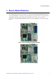
Figure 1. Intel
®
Server Board S5520HC/S5520HCT ...................................................................... 1
Figure 2. Intel
®
Server Board S5500HCV ...................................................................................... 1
Figure 3. Server Board Connector and Component Locations ...................................................... 4
Figure 4. Configuration Jumper Location ....................................................................................... 5
Figure 5. Back Panel Features ....................................................................................................... 6
Figure 6. Intel
®
Light-Guided Diagnostics ...................................................................................... 8
Figure 7. DIMM Sockets ............................................................................................................... 10
Figure 8. Intel
®
SAS Entry RAID Module ...................................................................................... 14
Figure 9. BIOS Recover Jumper .................................................................................................. 20
Figure 10. Password Clear Jumper .............................................................................................. 22
Figure 11. CMOS Clear Jumper ................................................................................................... 23
Figure 12 .Installing Memory ........................................................................................................ 24
Figure 13. Opening the Processor Socket Lever ......................................................................... 26
Figure 14. Opening the Processor Socket Load Plate ................................................................. 26
Figure 15. Removing the Processor Socket Protective Cover .................................................... 27
Figure 16. Remove Processor Protective Cover .......................................................................... 27
Figure 17. Install the processor .................................................................................................... 27
Figure 18. Close Load Plate and Socket Lever............................................................................ 28
Figure 19. Installing Processor Heatsink(s) ................................................................................. 30
Figure 20. Locating Active Heatsink Cable Connections ............................................................. 30
Figure 21. Locating and Removing the CMOS Battery ................................................................ 33
Tables
Table 1. Server Board Features ..................................................................................................... 2
Table 2. Configuration Jumpers ..................................................................................................... 5
Table 3. NIC LEDs .......................................................................................................................... 6
Table 4. Storage Mode Matrix ...................................................................................................... 13
Table 5. Keyboard Commands ..................................................................................................... 18
Table 6. Heatsink Requirements for Compatible Intel
®
Server Chassis ...................................... 29
Table 7. POST Error Beep Codes ................................................................................................ 34
Table 8. BIOS POST Error Beep Codes ...................................................................................... 40
Table 9. BMC POST Error Beep Codes ....................................................................................... 41
Table 10. Product Certification Markings ..................................................................................... 43