
Technical Product Specification

Power Sub-system Intel® Server System SC5650HCBRP TPS
Revision 1.2
Intel order number E81443-002
84
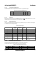
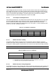
All outputs are measured with reference to the return remote sense signal (ReturnS). The 3.3V
and 5V outputs are measured at the remote sense point; all other voltages are measured at the
output harness connectors.
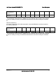
Table 45. Voltage Regulation Limits
Converter Output Tolerance MIN NOM MAX UNITS
+ 3.3VDC - 5% / +5% +3.14 +3.30 +3.46 V
DC
+ 5VDC - 5% / +5% +4.75 +5.00 +5.25 V
DC
+ 12VDC
(12V1/2/3/4)
- 5% / +5% +11.40 +12.00 +12.60 V
DC
- 12VDC - 10% / +10% -10.80 -12.00 -13.20 V
DC
+ 5VSB See Power Supply Specification; measured at the power distribution board
harness connectors.
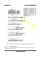
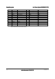
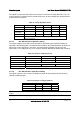
4.2.2.5 DC / DC Converters Dynamic Loading
The output voltages remain within limits specified for step loading and capacitive loading as
specified in the following table. The load transient repetition rate is tested between 50 Hz and 5
kHz at duty cycles ranging from 10%-90%. The load transient repetition rate is only a test
specification. The Δ step load may occur anywhere between MIN load and MAX load conditions.
Table 46. Transient Load Requirements
Output Max Δ Step Load Size Max Load Slew Rate Test Capacitive Load
+ 3.3VDC 5.0A 0.25 A/μs 250 μF
+ 5VDC 6.0A 0.25 A/μs 400 μF
+12VDC (12V1/2/3/4/5) See the Power Supply specification for details.
- 12VDC Not rated Not rated μF
+5VSB See the Power Supply specification for details.
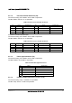
4.2.2.6 DC / DC Converter Capacitive Loading
All outputs of the DC / DC converter are stable and meet all requirements with the following
capacitive loading ranges.
Table 47. Capacitive Loading Conditions
Converter Output MIN MAX Units
+3.3VDC 250 6,800 μF
+5VDC 400 4,700 μF
-12VDC 1 350 μF
Note: Refer to the Power Supply specification for the equivalent data on +12V and +5VSB
output.