
Technical Product Specification

Power Sub-system Intel® Server System SC5650HCBRP TPS
Revision 1.2
Intel order number E81443-002
88
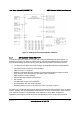
4.2.2.13 Soft Start Requirements
The power supply contains a control circuit which provides monotonic soft start for its outputs
without overstressing the AC line or any power supply components at any specified AC line or
load conditions. There is no requirement for rise time on the 5VSB, but the turn on/off is
monotonic.
4.2.3 Protection Circuits
Protection circuits inside the cage (and the power supply) cause the power supply’s main +12V
output to shut down, thereby forcing the remaining three outputs on the cage to shut down. If
the power supply latches off due to a protection circuit tripping, an AC cycle OFF for 15 sec min
and a PSON
#
cycle HIGH for 1 second will reset the power supply and the PDB.
4.2.3.1 Over-current Protection (OCP) / 240VA Protection
Each DC/DC converter output on the cage has individual OCP circuits. The PS+cage
combination will shut down and latch off after an over-current condition occurs. This latch is
cleared by toggling the PSON
#
signal or by an AC power interruption. The values are measured
at the PDB harness connectors. The DC/DC converters are not damaged from repeated power
cycling in this condition. The +12V output from the power supply is divided on the PDB into 5
channels and each channel is limited to 240VA of power except for +12V5 (+12V5 is not user
accessible). Current sensors and limit circuits are available to shut down the entire PS+PDB
combination if the limit is exceeded. The over-current limits are listed in the following table.
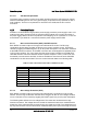
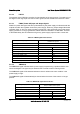
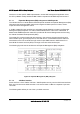
Table 51. Over-current Protection Limits / 240VA Protection
Output Voltage MIN OCP Trip Limits MAX OCP Trip Limits
+3.3V 110% min (= 26.4A min) 150% max (= 36A max)
+5V 110% min (= 33A min) 150% max (= 45A max)
-12V 0.625A 2.0A
+12V1 18A 20Amax
+12V2 18A 20Amax
+12V3 18A 20A max
+12V4 18A 20A max
+5VSB See the Power Supply specification for details.
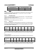
4.2.3.2 Over-voltage Protection (OVP)
Each DC/DC converter output on the cage has individual OVP circuits built in and is locally
sensed. The PS+cage combination will shut down and latch off after an over-voltage condition
occurs. This latch can be cleared by toggling the PSON
#
signal or by an AC power interruption.
The following table defines the over-voltage limits. The values are measured at the cage
harness connectors. The voltage does not exceed the maximum levels when measured at the
power pins of the output harness connector during any single point of fail. The voltage does not
trip any lower than the minimum levels when measured at the power pins of the cage connector.