
Technical Product Specification

Intel® Server System SC5650HCBRP TPS Power Sub-system
Revision 1.2
Intel order number E81443-002
89
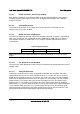
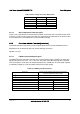
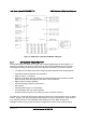
Table 52. Over-voltage Protection (OVP) Limits
Output Voltage OVP MIN (V) OVP MAX (V)
+3.3V 3.9 4.5
+5V 5.7 6.5
-12V -13.3 -14.5
+12V1/2/3/4 See Power Supply specification.
+5vsb See Power Supply specification.
4.2.3.3 Over Temperature Protection (OTP)
There is not a requirement of thermal sensor located on the cage and have OTP function itself.
If there is no OTP function build in the cage, the cage should be protected by the OTP function
in the module when over heated with no unrecoverable damage.
4.2.4 Control and Indicator Functions (Hard-wired)
The following sections define the input and output signals from the power distribution board.
Signals that can be defined as low true use the following convention:
signal# = low true
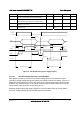
4.2.4.1 PSON# Input and Output Signals
The PSON
#
signal is required to remotely turn on/off the power supply. PSON
#
is an active low
signal that turns on the +3.3V, +5V, +12V, and -12V power rails. When this signal is not pulled
low by the system, or left open, the outputs (except for the +5VSB) turn off. This signal is pulled
to a standby voltage by a pull-up resistor internal to the power supply.
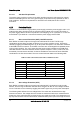
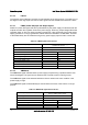
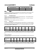
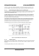
Table 53. PSON# Signal Characteristics
Signal Type
Accepts an open collector/drain input from the system.
Pull-up to VSB located in power supply.
PSON
#
= Low ON
PSON
#
= High or Open OFF
MIN MAX
Logic level low (power supply ON) 0V 1.0V
Logic level high (power supply OFF) 2.0V 5.25V
Source current, Vpson = low 4mA
Power up delay: T
pson_on_delay
5msec 400msec
PWOK delay: T
pson_pwok
50msec