
Technical Product Specification

Intel® Server System SC5650HCBRP TPS Power Sub-system
Revision 1.2
Intel order number E81443-002
91
Signal Type (Active Low)
Open collector / drain output from power supply.
Pull-up to VSB located in system.
Sink current, Alert# = high 50 μA
Alert# rise and fall time 100 μs
4.2.5 PMBus
The PMBus features included in this specification are requirements for ac/dc silver box power
supply for use in mainstream server systems. This specification is based on the PMBus
specifications parts I and II, revision 1.2.
4.2.5.1 Related Documents
PMBus™ Power System Management Protocol Specification Part I – General Requirements,
Transport And Electrical Interface; Revision 1.2
PMBus™ Power System Management Protocol Specification Part II – Command Language;
Revision 1.2
System Management Bus (SMBus) Specification Version 2.0
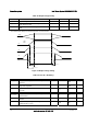
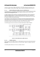
4.2.5.2 Addressing
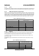
The power supply PMBus device address locations are shown below. For redundant systems
there are up to three signals to set the address location of the power supply once it is installed
in the system; Address2, Address1, Address0. For non-redundant systems the power supply
device address location should be B0h.
System addressing
Address2/Address1
/ Address0
0/0/0 0/0/1 0/1/0 0/1/1 1/0/0 1/0/1 1/1/0 1/1/1
PMBus device read
addresses 2
B0h/B1h
1
B2h/B3h B4h/B5h
B6h/B7h B8h/B9h BAh/BBh BCh/BDh BEh/BFh
1
Non-redundant power supplies will use the 0/0/0 address location
2
The addressing method uses the 7 MSB bits to set the address and the LSB to define whether
a device is reading or writing. The addresses defined above use 8 bits including the read/write
bit.
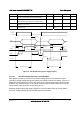
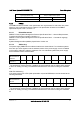
IPMI FRU Addressing
If the power supply has a FRU (field replaceable unit) serial EEPROM; it shall be located at the
following addresses.
System addressing
Address2/Address1/
Address0
0/0/0 0/0/1 0/1/0 0/1/1 1/0/0 1/0/1 1/1/0 1/1/1
FRU device addresses
2
A0h/A1h
1
A2h/A3h
A4hA5h A6h/A7h
A8h/A9h AAh/ABh ACh/ADh AEh/AFh
1
Non-redundant power supplies will use the 0/0/0 address location.
2
The addressing method uses the 7 MSB bits to set the address and the LSB to define whether
a device is reading or writing. The addresses defined above use 8 bits including the read/write
bit.