
Technical Product Specification

Intel® Server System SC5650HCBRP TPS Connector/Header Locations and Pin-outs
Revision 1.2
Intel order number E81443-002
153
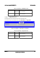
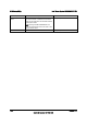
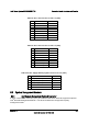
Table 96. CPU 1 Power Connector Pin-out (J9A1)
Pin Signal Color
1 GND of Pin 5 Black
2 GND of Pin 6 Black
3 GND of Pin 7 Black
4 GND of Pin 8 Black
5 +12 Vdc CPU1 Yellow / black
6 +12 Vdc CPU1 Yellow / black
7 +12 Vdc DDR3_CPU1
Yellow / black
8 +12 Vdc DDR3_CPU1
Yellow / black
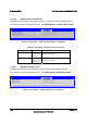
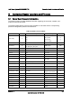
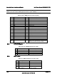
Table 97. CPU 2 Power Connector Pin-out (J9K1)
Pin Signal Color
1 GND of Pin 5 Black
2 GND of Pin 6 Black
3 GND of Pin 7 Black
4 GND of Pin 8 Black
5 +12 Vdc CPU2 Yellow / black
6 +12 Vdc CPU2 Yellow / black
7 +12 Vdc DDR3_CPU2 Yellow / black
8 +12 Vdc DDR3_CPU2 Yellow / black
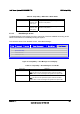
Table 98. Power Supply Auxiliary Signal Connector Pin-out (J9K2)
Pin Signal Color
1 SMB_CLK_FP_PWR_R Orange
2 SMB_DAT_FP_PWR_R Black
3 SMB_ALRT_3_ESB_R Red
4 3.3 V SENSE- Yellow
5 3.3 V SENSE+ Green
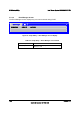
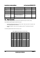
8.3 System Management Headers
8.3.1 Intel
®
Remote Management Module 3 Connector
A 34-pin Intel
®
RMM3 connector (J1C1) is included on the server board to support the optional
Intel
®
Remote Management Module 3. The server board does not support third-party
management cards.