
Technical Product Specification

Intel® Server System SC5650HCBRP TPS Connector/Header Locations and Pin-outs
Revision 1.2
Intel order number E81443-002
155
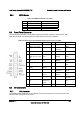
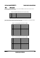
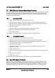
8.3.4 SGPIO Header
Table 102. SGPIO Header Pin-out (J1G2)
Pin Signal Name
Description
1 SGPIO_CLOCK SGPIO Clock Signal
2 SGPIO_LOAD SGPIO Load Signal
3 SGPIO_DATAOUT0 SGPIO Data Out
4 SGPIO_DATAOUT1 SGPIO Data In
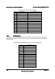
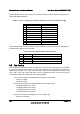
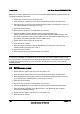
8.4 Front Panel Connector
The server board provides a 24-pin SSI front panel connector (J1B3) for use with Intel
®
and
third-party chassis. The following table provides the pin-out for this connector.
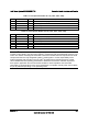
Table 103. Front Panel SSI Standard 24-pin Connector Pin-out (J1B3)
Pin Signal Name Description Pin
Signal Name Description
1 P3V3_STBY
(Power_LED_Anode)
Power LED + 2 P3V3_STBY Front Panel
Power
3 Key No Connection 4 P5V_STBY (ID
LED Anode)
ID LED +
5 FP_PWR_LED_N Power LED - 6 FP_ID_LED_BUF_
N
ID LED -
7 P3V3
(HDD_ACTIVITY_Anod
e)
HDD Activity
LED +
8 FP_LED_STATUS_
GREEN_N
Status LED
Green -
9 LED_HDD_ACTIVITY_
N
HDD Activity
LED -
10 FP_LED_STATUS_
AMBER_N
Status LED
Amber -
11 FP_PWR_BTN_N Power Button 12 NIC1_ACT_LED_N NIC 1 Activity
LED -
13 GND (Power Button
GND)
Power Button
Ground
14 NIC1_LINK_LED_N NIC 1 Link LED -
15 BMC_RST_BTN_N Reset Button 16 SMB_SENSOR_3V
3STB_DATA
SMB Sensor
DATA
17 BND (Reset GND) Reset Button
Ground
18 SMB_SENSOR_3V
3STB_CLK
SMB Sensor
Clock
19 FP_ID_BTN_N ID Button 20 FP_CHASSIS_INTR
U
Chassis
Intrusion
21 FM_SIO_TEMP_SENSO
R
Front Panel
Temperature
Sensor
22 NIC2_ACT_LED_N NIC 2 Activity
LED -
23 FP_NMI_BTN_N NMI Button 24 NIC2_LINK_LED_N NIC 2 Link LED -
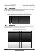
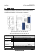
8.5 I/O Connectors
8.5.1 VGA Connector
The following table details the pin-out definition of the VGA connector (J7A1) that is part of the
stacked video / serial port A connector.