
Technical Product Specification

Intel® Server System SC5650HCBRP TPS Connector/Header Locations and Pin-outs
Revision 1.2
Intel order number E81443-002
157
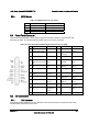
8.5.3 SATA Connectors
The server board provides up to six SATA connectors: SATA-0 (J1G5), SATA-1 (J1G4), SATA-
2 (J1G1), SATA-3 (J1F4), SATA-4 (J1F1), and SATA-5 (J1E3).
The pin configuration for each connector is identical and defined in the following table.
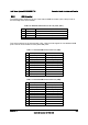
Table 106. SATA / SAS Connector Pin-out (J1E3, J1G1, J1G4, J1G5, J1F1, J1F4)
Pin Signal Name
Description
1 GND Ground
2 SATA TX_P_C Positive side of transmit differential pair
3 SATA TX_N_C Negative side of transmit differential pair
4 GND Ground
5 SATA _RX_N_C Negative side of receive differential pair
6 SATA _RX_P_C Positive side of receive differential pair
7 GND Ground
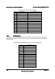
8.5.4 SAS Module Slot
The server board provides one SAS module slot (J2J1) to support the Intel
®
SAS Entry RAID
Module AXX4SASMOD card. The following table defines the pin-out.
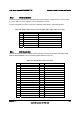
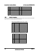
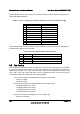
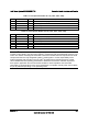
Table 107. SAS Module Slot Pin-out (J2J1)
Pin Name Pin
Name
1 P3V3_AUX 2 RST_LPC_SAS_N
3 SW_RAID_MODE 4 GND
5 PE_ICH10_SAS_SW_C_TP0 6 PE_ICH10_SAS_SW_C_TN0
7 GND 8 GND
9 PE_ICH10_SAS_SW_C_TP1 10 PE_ICH10_SAS_SW_C_TN1
11 GND 12 GND
13 PE_ICH10_SAS_SW_C_TN2 14 PE_ICH10_SAS_SW_C_TN2
15 GND 16 GND
17 PE_ICH10_SAS_SW_C_TN3 18 PE_ICH10_SAS_SW_C_TN3
19 GND 20 FM_SAS_PRSNT_N
21 PE_WAKE_N 22 FM_SAS_RST_N
23 P3V3 24 PE_RXN<2>
25 P3V3 26 P3V3_AUX
27 GND 28 PE_ICH10_SAS_SW_RXP0
29 PE_ICH10_SAS_SW_RXN0 30 GND
31 GND 32 PE_ICH10_SAS_SW_RXP1
33 PE_ICH10_SAS_SW_RXN1 34 GND