
Technical Product Specification


Power Sub-system Intel® Server System SC5650HCBRP TPS
Revision 1.2
Intel order number E81443-002
74
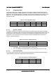
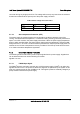
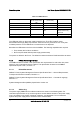
Table 34. LED Indicators
Power Supply Condition Status LED
(AC OK / Power Supply
Fail)
Power Led
(Power Good)
Remarks
AC Power Off OFF OFF
AC Power On in Standby Mode Green OFF
AC On and All Outputs in Normal Mode Green Green
Any DC Outputs Short Circuit Green
OFF
Power Distribution
Board protection only;
module OK
DC Fan Not Spinning Amber OFF Module protection only
OTP Amber Green Send out alert signal
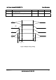
The LEDs are visible on the power supply’s exterior face. The LEDs’ location meets
Electrostatic Discharge (ESD) requirements. LEDs are securely mounted in such a way that
incidental pressure on the LEDs does not cause them to be displaced.
Bits allow the LED states to be forced via the SMBus. The following capabilities are required:
• Force Amber ON for failure conditions.
• No Force (LED state follows power supply present state)
The power-on default is ‘No Force’. The default is restored whenever PSON transitions to assert.
4.1.6 PMBus Monitoring Interface
The PMBus features included in this specification are requirements for ac/dc silver box power
supply for use in mainstream server systems. This specification is based on the PMBus
specifications parts I and II, revision 1.2.
4.1.6.1 Related Documents
PMBus™ Power System Management Protocol Specification Part I – General Requirements,
Transport And Electrical Interface; Revision 1.2
PMBus™ Power System Management Protocol Specification Part II – Command Language;
Revision 1.2
System Management Bus (SMBus) Specification Version 2.0
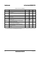
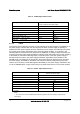
4.1.6.2 Addressing
The power supply PMBus device address locations are shown in the following table. For
redundant systems there are up to three signals to set the address location of the power supply
once it is installed in the system: Address2, Address1, and Address0. For non-redundant
systems the power supply device address location should be B0h.