
Enclosure Management Cabling for Pedestal Systems with Hot-Swap Drive Enclosures

Enclosure Management Cabling for Pedestal Systems with Hot-Swap Drive Enclosures
2
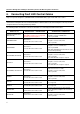
3. Connecting One Non-Expander Backplane
You must connect the following cables to the backplane:
SATA/SAS data cables:
− With 4-drive Non-expander backplane, RAID controller ports 0-3 must be connected to the Non-
expander backplane. Make sure port 0 is connected to slot 0, port 1 to slot 1, and so on.
− With 6-drive Non-expander backplane, RAID controller ports 0-5 must be connected to the Non-
expander backplane ports. Make sure port 0 is connected to slot 0, port 1 to slot 1, and so on.
Power cables
IPMB cable for updating the hot-swap controller firmware, reading the temperature, and detecting drive
presence:
− Cable: Use the 4-pin IPMB cable provided with a hot-swap drive enclosure.
− Backplane Connector: Use the white 4-pin IPMB connector on the backplane.
− Mainboard Connectors: Use the white 4-pin HSBP_A connector on the server board. Do not use the
HSBP_B connector.
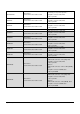
Connect the Fault LED control cable (for drive identification and drive fault/rebuild indication with amber
drive LEDs) according to the instructions for your RAID controller provided in Section 6.
4. Connecting One Non-expander + One Expander
Backplane
You must connect the following cables to each backplane:
SATA/SAS data cables:
− With 4-drive Non-expander backplane, RAID controller ports 0-3 must be connected to the Non-
expander backplane. Make sure port 0 is connected to slot 0, port 1 to slot 1, and so on.
− With 6-drive Non-expander backplane, RAID controller ports 0-5 must be connected to the Non-
expander backplane ports. Make sure port 0 is connected to slot 0, port 1 to slot 1, and so on.
Power cables
IPMB cable for updating the hot-swap controller firmware, reading the temperature, and detecting drive
presence:
− Cable: Use the 4-pin IPMB cable provided with a hot-swap drive enclosure.
− Backplane Connector: Use the white 4-pin IPMB connector on the backplane.
− Mainboard Connectors: Use the white 4-pin HSBP_A connector on the server board to connect the six-
drive backplane. Use the white 4-pin HSBP_B connector to connect the four-drive backplane.
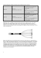
Connect the Fault LED control cable to the Non-Expander backplane (for drive identification and drive
fault/rebuild indication with amber drive LEDs) according to the instructions for your RAID controller
provided in Section 6.
5. Connecting Two Non-Expander Backplanes
Only Intel
®
RAID Controller SRCSASPH16I can support Fault LED control with two Non-expander backplanes.
You must connect the following cables to the backplane:
SATA/SAS data cables: