
Enclosure Management Cabling for Pedestal Systems with Hot-Swap Drive Enclosures

Enclosure Management Cabling for Pedestal Systems with Hot-Swap Drive Enclosures
6
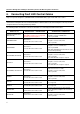
RMS2LL080
SAS in-band.
No drive LED control cable needed.
Option 1:
RAID module connector: J1A1 (SES), white
Backplane connector: SES, white
Cable: 3-pin SES
Option 2:
RAID module connector: J1A2 or J1B2 (SGPIO),
black
Backplane connector: SGPIO, black
Cable: 4-pin SGPIO
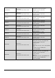
RMS2LL040
SAS in-band.
No drive LED control cable needed.
Option 1:
RAID module connector: J1A1 (SES), white
Backplane connector: SES, white
Cable: 3-pin SES
Option 2:
RAID module connector: J1A2 (SGPIO), black
Backplane connector: SGPIO, black
Cable: 4-pin SGPIO
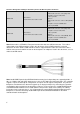
Note: Below cable is SFF8087 to Four-port Internal Cable with one SGPIO Connector. This cable is
shipped with some RAID controllers listed in this document. Refer to RAID controllers’ technical
documents for more details. RAID controllers that are shipped with this cable can connect the cable’s
SGPIO connector to the SGPIO header on the backplanes or midplanes listed in this document, so as to
enable fault LED control.
Note: Intel® RAID Expander Card RES2SV240 has twenty-four independent ports supporting 6Gb/s, 3
Gb/s, or 1.5Gb/s SAS and SATA data transfers using six SFF-8087 mini-SAS connectors. This controller
supports 4 inputs and 20 outputs configuration, or 8 inputs and 16 outputs configuration. The pedestal
backplanes mentioned in this document supports up to 10 physical drives by connecting the expander
card to both 6-drive and 4-drive hot-swap drive enclosures. Refer to Figure 4 in Intel® RAID Expander
Card RES2SV240 Hardware User’s Guide (E93121-0xx) for more details of the cabling. For cabling
inside other Intel’s pedestal chassis, it is recommended to connect RAID controller/module directly to
backplanes, instead of connecting Intel® RAID Expander Card RES2SV240 between the RAID
controller/module and backplane.