
Service Guide

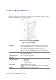

Server System Features
6 Intel
®
Server System SC5650HCBRP Service Guide
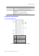
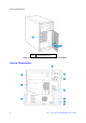
H
Location to Install Padlock Loop
I
Rear Chassis Fan Assembly
J
External SCSI Port Knockout
Figure 5. Back Panel Components
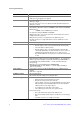
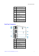
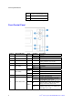
Front Control Panel
Callout Button/LED Name Color Condition Description
A Power LED Green
On Power on
Off Power off
B Power Button N/A N/A Powers the system on or off
C NMI Button N/A N/A
Used to force system halt and dump
memory contents to screen or file
D Reset Button N/A N/A Reboots and initializes the system
E NIC1 Activity
Green
On Linked
Blink LAN activity
Off Idle
F NIC2 Activity
Green
On Linked
Blink LAN activity
Off Idle
G Hard Drive Activity Green Blink Hard drive activity
H System Status LED
Green
On System booted and ready
Blink
System ready, but degraded: some CPU
fault, DIMM killed, and so forth
Amber
On
Critical alarm: Critical power module failure,
critical fan failure, voltage (power supply),
voltage, thermal fault, and so forth
Blink
Non-critical failure: Redundant fan failure,
redundant power failure, non-critical power
and voltage, and so forth