
Service Guide

Server System Features
Intel®
Server System SC5650HCBRP Service Guide 9
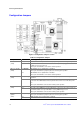
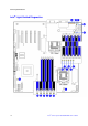
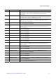
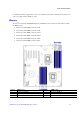
Callout Description Callout Description
Universal
B Intel
®
RMM3 Slot X System Fan 1 Header (6-pin)
C Slot 2, PCI Express* Gen 1 x4 (x8 Mechanically) Y Main Power Connector
D Low-profile USB Solid State Drive Header Z LCP/IPMB Header
E Slot 3, PCI Express* Gen2 x8 AA Type A USB Port
F Slot 4, PCI Express* Gen2 x8 BB SATA SGPIO Header
G Slot 5, PCI Express* Gen2 x8 CC SATA Port 0
H Slot 6, PCI Express* Gen2 x8 (x16 Mechanically) DD SATA Port 1
I Battery EE HSBP_B
J Back Panel I/O Ports FF SATA Port 2
K Diagnostic and Identify LED’s GG HSBP_A
L System Fan 5 Header (4-pin) HH SATA Port 3
M
Power Connector for Processor 1 and Memory
attached to Processor 1
II SATA Software RAID 5 Key Header
N Processor 1 Fan Header (4-pin) JJ Chassis Intrusion Header
O DIMM Sockets of Memory Channel A, B, and C KK SATA Port 4
P
Power Connector for Processor 2 and Memory
attached to Processor 2
LL SATA Port 5
Q Auxiliary Power Signal Connector MM
HDD Activity LED Header (Connect to
Add-in Card HDD Activity LED
Header)
R Processor 2 Fan Header (4-pin) NN
USB Connector (9-pin, for front panel
USB ports)
S DIMM Sockets of Memory Channel D, E, and F OO USB Connector (9-pin)
T SAS Module Slot PP Front Control Panel header
U System Fan 3 Header (6-pin) QQ DH-10 Serial B header
V System Fan 4 Header (6-pin)
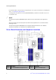
Figure 8. Server Board Connector and Component Locations