
Service Guide

Hardware Installations and Upgrades
Intel® Server System SC5650HCBRP Service Guide 41
2. Power down the server and unplug all peripheral devices and the AC power cable.
3. Remove the left side cover. For instructions, see “Removing the Left Side Cover”.
4. Remove the front bezel assembly. For instructions, see “Removing the Front Bezel Assembly”.
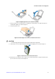
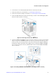
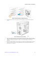
5. Remove the EMI shield from the 5.25-in device drive bay (see letter “A” in the following figure). Move
latch to the “unlock” position (see letter “B”).
Figure 36. Removing 5.25-inch drive EMI Shield
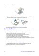
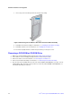
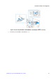
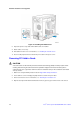
6. Insert the CD-ROM or DVD-ROM drive into the 5.25-in device drive bay (see letter “C” in the following
figure). Line up holes in CD-ROM drive with holes in chassis (see letter “D”). Move latch to the “lock”
position (see letter “E”). Connect power (P5 or P6 connector from the power supply. An additional 4-
pin IDE male-to SATA 15-point power cables adapter may be needed if the CD-ROM or DVD-ROM
does not have a 4-pin power connector.) and data cables to the rear of the CD-ROM or DVD-ROM
drive (see letter “F”).
Figure 37. Installing CD-ROM or DVD-ROM Drive (SATA Optical Drive is shown)