
Service Guide

Hardware Installations and Upgrades
Intel® Server System SC5650HCBRP Service Guide 65
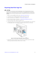
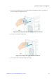
Figure 76. Securing Hot Swap Power Supply Cage to Inside of Chassis
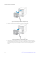
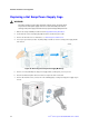
13. Route and connect the P1, P2, P3, and P4 cables to the server board.
14. Route the P5 and P6 cables to the PCI Express* graphic cards.
15. Route the P9 and P10 cables to the 5.25-in. removable media device bays and connect to installed
devices.
16. Route the P11, P12, P13, and P14 cables to the hard drive cage and connect power cables to installed
devices.
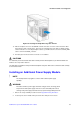
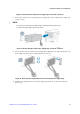
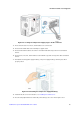
17. Reinstall the hot swap power supply module(s). The power supply module(s) clicks into place when
properly seated.
Figure 77. Reinstalling Hot Swap Power Supply Module(s)
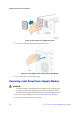
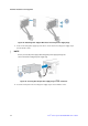
18. Install the left side cover. For instructions, see “Installing the Left Side Cover”.
19. Reconnect all peripheral devices and the AC power cable(s) to the server. Power up the server.