
Technical Product Specification


Intel® Server System SR2612UR TPS Cooling Subsystem
Revision 1.3
Intel order number E76293-003
19
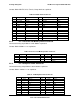
3.6 Output Connectors
The power distribution board provides a cable harness providing connectors to the various
system boards. The harness size, connectors, and pin outs are shown in the following tables.
Listed or recognized component appliance wiring material (AVLV2), CN, rated 105°C minimum,
300 VDC minimum is used for all output wiring.
Table 7. Power Harness Cable Definitions
Connector #
No of
Pins
Description
P1 1x5 Server Board Signal Connector
P2 2x12 Main Power Connector to Server Board
P3 2x4 Processor and Memory Power Connector
P4 2x12 Backplane Power Connector
P5 2x2 Auxiliary Baseboard Power Connector 1
P6 2x2 Auxiliary Baseboard Power Connector 2
P7* 1x5 SATA Hard Disk Power Connector 1
P8* 1x5 SATA Hard Disk Power Connector 2
P9* 1x5 SATA Peripheral Power Connector
* These connectors are daisy-chained to one cable
3.6.1 P1 – Power Signal Connector
Connector housing: 5-pin Molex* 50-57-9405 or equivalent
Contact: Molex* 16-02-0088 or equivalent
Table 8. P1 Power Signal Connector
PIN
Signal
24 AWG Colors
1
SMBus Clock
White/Green Stripe
2 SMBus Data White/Yellow Stripe
3
SMBAlert
White
4
ReturnS
Black/White Stripe
5
3.3RS
Orange/White Stripe
3.6.2 P2 – Server Board Power Connector
Connector housing: 24-pin Molex* Mini-Fit Jr.
39-01-2240 or equivalent