
Technical Product Specification


Cooling Subsystem Intel® Server System SR2612UR TPS
22 Revision 1.3
Intel order number E76293-003
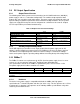
Table 15. AC Input Rating
Parameter
Minimu
m
Rated
Maximu
m
Line Voltage
(110)
90 V
rms
100 - 127 V
rms
140 V
rms
Line Voltage
(220)
180 V
rms
200 - 240 V
rms
264 V
rms
Frequency
47 Hz
50/60 Hz
63 Hz
Notes:
1. The maximum input line current shall be less than 9.0 Amps RMS at 100VAC when measured under the
standard test condition
3.7.3 AC Line Dropout/Holdup
An AC line dropout is defined to be when the AC input drops to 0 VAC at any phase of the AC
line for any length of time. During an AC dropout of one cycle or less, the power supply must
meet dynamic voltage regulation requirements over the rated load. If the AC dropout lasts
longer than one cycle, the power supply should recover and meet all turn-on requirements. The
power supply must meet the AC dropout requirement over rated AC voltages, frequencies, and
output loading conditions. Any dropout of the AC line does not cause damage to the power
supply.
Minimum Output Holdup: 12 ms
Minimum Standby Output Holdup: 20 ms
3.7.4 AC Inrush
The maximum inrush current, excluding X-Caps, shall be less than 25 Amps-peak under all
conditions.
The inrush current shall decay to its normal operating current in less than 200msec. The inrush
current shall be less than 60% of the I
2
t rating of all the components in series with the charging
circuits for the input electrolytic capacitors.
For any conditions during turn-on, the inrush current will not open the primary input fuse or
damage any other components.
3.8 Protection Circuits
Protection circuits inside the PDB and the power supply cause the power supply’s main +12 V
output to shut down, or cause a shutdown of any of the three outputs on the PDB. Any one of
these shutdowns results in shutting down the entire power supply / PDB combination. If the
power supply latches off due to a protection circuit tripping, an AC cycle OFF for 15 seconds
resets the power supply and the PDB.
3.8.1 Over-current Protection (OCP)
Each DC/DC converter output on the PDB has individual OCP protection circuits. The power
supply and power distribution board (PS and PDB) shut down and latch off after an over-current
condition occurs. This latch is cleared by toggling the PSON# signal or by an AC power
interruption. The over-current limits are measured at the PDB harness connectors.