
Technical Product Specification


Intel® Server System SR2612UR TPS System Board Interconnects
Revision 1.3
Intel order number E76293-003
35
Table 24. Backplane Power Supply Pin-out (J23)
Pin Signal Pin Signal
1 +3.3V 13 +3.3V
2 +3.3V 14 +12V
3 GND 15 GND
4 +5V 16 GND
5 GND 17 GND
6 +5V 18 GND
7 GND 19 GND
8 +12V 20 +12V
9
Fan Power
(+12V)
21 +5V
10
Fan Power
(+12V)
22 +5V
11 +12V 23 +5V
12 +3.3V 24 GND
Table 25. SAS/SATA Hard Drive Connector Pin-outs (J1, J2, …, J12)
Pin Signal Pin Signal
1 GND 17 +3.3V
2
IO1_TO_DR#+ (# = 1…12)
18 GND
3
IO1_TO_DR#- (# = 1…12)
19 NC
4 GND 20 GND
5
DR#_TO_IO1- (# = 1…12)
21 +5V
6
DR#_TO_IO1+ (# = 1…12)
22 +5V
7 GND 23 +5V
8 GND 24 GND
9
IO2_TO_DR#+ (# = 1…12)
25
DR#_ACTIVITY_LED_L (# = 1…12)
10
IO2_TO_DR#- (# = 1…12)
26 GND
11 GND 27 +12V
12
DR#_TO_IO2- (# = 1…12)
28 +12V
13
DR#_TO_IO2+ (# = 1…12)
29 +12V
14 GND 30 GND
15 +3.3V 31 GND
16 +3.3V
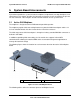
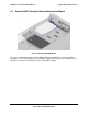
5.2.1 Hard Drive Activity and Fault LEDs
Each populated disk drive carrier has three LEDs that indicate the status of the disk drive, as
described in the following table.