
Technical Product Specification


Intel® Server System SR2612UR TPS Peripheral and Hard Drive Subsystem
Revision 1.3
Intel order number E76293-003
39
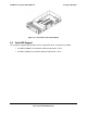
Figure 23. Drive Bay Overview
6.1 Slimline Optical Drive Bay
The system provides a slimline drive bay designed to support a single slimline SATA optical
drive. For a list of supported drives, refer to the Server Configurator Tool available at:
http://serverconfigurator.intel.com/default.aspx
The optical drive is mounted to a tool-less assembly latch that allows for easy installation and
attachment to the system. Once it is inserted into the system, the assembly locks into place. It
is not hot-swappable. For removal, you must power down the system, remove the system’s top
cover, and disengage the locking latch. For additional details, see the Intel
®
Server System
SR2612UR Service Guide.
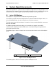
Figure 24. Slimline Optical Drive Assembly
The SATA Optical drive plugs directly into the backplane using industry standard 13-pin SATA
connector. This SATA channel is routed from the USB to the SATA converter located on the
backplane. The optical drive is seen as a USB device in the system.
6.2 Hard Drive Bays
The system supports up to 12 hot-swap 3.5-inch SAS or SATA hard disk drives. Hard drives are
mounted to hot-swap drive trays for easy insertion to or extraction from the drive bay. Two
additional fixed mount 2.5-inch drives are supported with an internal drive cage.
6.2.1 Hot-swap Drive Carriers
Each hard drive must be mounted to a hot-swap drive carrier, making insertion and extraction of
the drive from the system very simple. Each drive carrier has its own dual-purpose latching
mechanism, which is used to both insert/extract drives from the system and lock the carrier in
place. Each drive tray supports a light pipe that provides a drive status indicator. The light pipe
is located on the backplane, which you can view from the front of the system.