Intel® Server Board S875WP1-E Product Guide A Guide for Technically Qualified Assemblers of Intel® Identified Subassemblies/Products Order Number: C32693-002
Important Safety Instructions Read all caution and safety statements in this document before performing any of the instructions. See also Intel Server Boards and Server Chassis Safety Information on the Resource CD and/or at http:\\support.intel.com. Disclaimer Intel Corporation (Intel) makes no warranty of any kind with regard to this material, including, but not limited to, the implied warranties of merchantability and fitness for a particular purpose.
Contents 1 Server Board Features................................................................................... 9 Server Board Connector and Component Locations ............................................................ 11 Back Panel Connectors................................................................................................ 12 Front Panel Connectors ............................................................................................... 12 Processor ..............................
BIOS ..................................................................................................................................... 33 PCI Auto Configuration................................................................................................. 33 IDE Auto Configuration................................................................................................. 33 BIOS Updates ..............................................................................................................
3 Configuration Software and Utilities ......................................................... 63 Updating the BIOS with the Intel® Flash Memory Update Utility .......................................... 63 Obtaining the BIOS Update File ................................................................................... 63 Recording the Current BIOS Settings .......................................................................... 64 Creating Bootable Media ..............................................
Server Board Resources..................................................................................................... 104 Memory Map .............................................................................................................. 104 DMA Channels ........................................................................................................... 104 I/O Map .....................................................................................................................
Figures Figure 1. Server Board Components .......................................................................................... 11 Figure 2. Back Panel Connectors ............................................................................................... 12 Figure 3. Front Panel Connectors............................................................................................... 12 Figure 4. Location of the Standby Power Indicator LED CR7J1 .................................................
Table 21. Table 22. Table 23. Table 24. Table 25. Table 26. Table 27. Table 28. Table 29. Table 30. Table 31. Table 32. Table 33. Table 34. Table 35. Table 36. Table 37. Table 38. Table 39. Table 40. Table 41. Table 42. Table 43. Table 44. Table 45. Table 46. Table 47. Table 48. viii Boot Configuration Submenu ........................................................................ 73 Peripheral Configuration Submenu ...............................................................
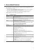
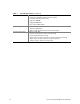
1 Server Board Features This chapter briefly describes the main features of Intel® Server Board S875WP1-E. This server board is available in two options: • The server board S875WP1 includes dual-channel Serial ATA support with two Serial ATA connectors. Support for RAID 0 and 1 support is planned. • The server board S875WP1LX includes an additional four-port Serial ATA controller to support a total of six Serial ATA connectors with support for RAID 0, 1, and 10.
Table 1.
Server Board Connector and Component Locations A B C D E F G CC H BB I AA J K Z L Y M X N W V O P U S T A. B. C. D. E. F. G. H. I. J. K. L. M. N. O. P. Q.
Back Panel Connectors The back panel connectors are color-coded in compliance with PC 99 recommendations. C F G A B D E H I TP00183 A. B. C. D. E. PS/2 mouse PS/2 keyboard Parallel port Serial port A Video port F. G. H. I. NIC 1 (1 Gb) NIC 2 (10/100 Mb) USB ports 1 and 2 USB ports 3 and 4 Figure 2. Back Panel Connectors Front Panel Connectors Figure 3 shows the location of the front panel connectors. A TP00184 B A. B. SCSI LED Header Front Panel Header Figure 3.
Processor The S875WP1-E server board supports a single Intel Pentium 4 processor with an mPGA478 socket. The processor connects to the server board through the mPGA478 socket. The Intel Pentium 4 processor can be removed and replaced to accommodate a supported higher speed processor. The server board S875WP1-E supports the following processors. Table 2. Supported Processors Type ✏ Designation System Bus L2 Cache Size Pentium 4 processor with Hyper- 2.40, 2.60, 2.80, and 3.
• Support for 128 Mb, 256 Mb, and 512 Mb memory technologies for the following memory configurations: Up to 1.0 GB utilizing 128 Mb technology Up to 2.0 GB utilizing 256 Mb technology Up to 4.0 GB utilizing 512 Mb technology Only DIMMs tested and qualified by Intel or a designated memory test vendor will be supported on the S875WP1-E server board. Note that all DIMMs are supported by design, but only fully qualified DIMMs will be supported.
Intel 82801EB I/O Controller Hub (ICH5-R) The Intel 82801EB ICH5-R has these features: • Upstream Hub Interface to the MCH • Integrated IDE controller (supports two Ultra ATA-100/66 mode, Ultra DMA 33 mode, and PIO mode). • Integrated SATA controller supports two SATA devices with transfer speeds up to 150 MB/s and independent DMA operation on the two ports • One USB 2.0-compliant host controller that supports all six USB ports • SMBus 2.
AGP Connector AGP is a high-performance interface for graphics-intensive applications. AGP is independent of the PCI bus and is intended for exclusive use with graphical display devices. The AGP bus follows the AGP 3.0 specification. The AGP connector on the server board S875WP1-E supports the following: • 2X, 4X, or 8X AGP protocol • 1.5 V add-in cards only • Maximum bus bandwidth of 2.13 GB/sec ✏ NOTE The AGP connector is keyed for 1.5 V AGP cards only. Do not attempt to install a legacy 3.3 V AGP card.
Table 3.
Serial Port The server board S875WP1-E has one serial port connector and one serial port header. The serial port A connector is located on the back panel. The serial ports’ NS16C550-compatible UART supports data transfers at speeds up to 115.2 kb/s with BIOS support. A DH10 10-pin serial header is available on the baseboard for an option Serial B port. Parallel Port The 25-pin D-Sub parallel port connector is located on the back panel.
USB High-Speed USB 2.0 Support ✏ NOTES Use a shielded cable that meets the requirements for a full-speed USB device. Computer systems that have an unshielded cable attached to a USB port might not meet FCC Class B requirements, even if no device or a lowspeed USB device is attached to the cable. USB devices are limited to USB 1.1 transfer rates prior to operating system and driver initialization. The server board supports up to six USB 2.0 ports via the ICH5. Four ports are routed to the back panel.
Legacy USB support operates as follows: 1. When the user applies power to the computer, legacy support is disabled. 2. POST begins. 3. Legacy USB support is enabled by the BIOS allowing the user to use a USB keyboard to enter and configure the BIOS Setup program and the maintenance menu. 4. POST completes. 5. The operating system loads. While the operating system is loading, USB keyboard and mice are recognized and may be used to configure the operating system.
Device IDs (IDSEL) Each device under the PCI hub bridge has its IDSEL signal connected to one bit of AD[31:16], which acts as a chip select on the PCI bus segment in configuration cycles. This determines a unique PCI device ID value for use in configuration cycles. The following table shows each IDSEL value for the PCI bus devices and the corresponding device description. Table 5.
IDE Interfaces The ICH5-R IDE controller has two independent bus-mastering IDE interfaces that can be independently enabled. The interface handles the exchange of information between the processor and peripheral devices like hard disks and CD-ROM drives.
Network Interface Controller (NIC) The server board S875WP1-E supports two Network Interface Controllers (NICs), one that runs at 10/100Mb and is based on the Intel 82562ET NIC and the other that runs at one gigabit and is based on the Intel 82547EI NIC. When looking at the rear of the chassis, the gigabit NIC is at the left (closest to the video port) and the 10/100Mb NIC is at the right. You can disable either or both NICs through BIOS Setup.
Table 7 describes the LED states when the board is powered up and the 82547EI 10/100/1000 Gigabit Ethernet LAN subsystem is operating. Table 7. LED Color Green (left LED) Bi-color LED (right LED) 10/100/1000 Gigabit Ethernet LAN Connector LEDs LED State Indicates Off LAN link is not established. On (steady state) LAN link is established. On (brighter and pulsing) The computer is communicating with another computer on the LAN. Off 10 Mbit/sec data rate is selected.
ACPI features include: • Plug and Play (including bus and device enumeration) • Power management control of individual devices, add-in boards (some add-in boards may require an ACPI-aware driver), video displays, and hard disk drives • Methods for achieving less than 15-watt system operation in the power-on/standby sleeping state • A soft-off feature that enables the operating system to power-off the computer • Support for multiple wake-up events • Support for a front panel power and sleep mode switch The S
Wake-up Devices and Events CAUTION For LAN wake capabilities, the 5 V standby line for the power supply must be capable of providing adequate +5 V standby current. Failure to provide adequate standby current when implementing LAN wake capabilities can damage the power supply. Table 9 provides an overview of the devices or events that can wake the computer from specific states. Table 9.
Resume on Ring Resume on Ring enables telephony devices to access the computer when it is in a power-managed state. The operation of Resume on Ring wakes the system from the S1 or S3 sleep states when a signal is sent to the serial port at the rear or the chassis or to an internally installed modem.
Power Connector When used with an ATX12V or EPS12V compliant power supply that supports remote power on/off, the S875WP1-E server board can turn off the system power through software control. When the system BIOS receives the correct command from the operating system, the BIOS turns off power to the computer.
Instantly Available PC Technology CAUTION For Instantly Available PC technology, the +5 V standby line for the power supply must be capable of providing adequate +5 V standby current. Failure to provide adequate standby current when implementing Instantly Available PC technology can damage the power supply. The S875WP1-E server board supports the PCI Bus Power Management Interface Specification.
Hardware Management and Monitoring The Hardware Management features enable the board to be compatible with the Wired for Management (WfM) specification. The board has several hardware management features, including the following: • Remote temperature sensing near the Vreg • Power supply monitoring (+5 V, +3.3 V, 3.3 VSB, +1.5 V, and VCCP) to detect levels above or below acceptable values • Fan monitoring though four fan tachometer inputs.
Password Security The BIOS includes security features that restrict whether the BIOS Setup program can be accessed and who can boot the server. A supervisor password and a user password can be set for the Setup menu and for booting the server, with the following restrictions: • The supervisor password gives unrestricted access to view and change all Setup options. If only the supervisor password is set, pressing at the password prompt of Setup gives the user restricted access to Setup.
Real-Time Clock, CMOS SRAM, and Battery The real-time clock provides a time-of-day clock and a multi-century calendar with alarm features. The real-time clock supports 256 bytes of battery-backed CMOS SRAM in two banks that are reserved for BIOS use. A coin-cell battery (CR2032) powers the real-time clock and CMOS memory. When the computer is not plugged into a wall socket, the battery has an estimated life of three years.
4. 5. 6. 7. 8. 9. Reattach the AC power cables and power on the server. Power down the server and again remove all AC power cables. Replace the jumper at jumper block J8G1 so that it covers pins 1 and 2. Replace the chassis cover and re-attach the AC power cables. Power on the server. Reconfigure settings as necessary. BIOS The S875WP1-E server board uses an Intel/AMI BIOS that is stored in the Firmware Hub (FWH) and can be updated using a disk-based program.
To use ATA-66/100 features the following items are required: • An ATA-66/100 peripheral device • An ATA-66/100 compatible cable • ATA-66/100 operating system device drivers ✏ NOTE ATA-66/100-compatible cables are backward-compatible with drives using slower IDE transfer protocols. If an ATA-66/100 disk drive and a disk drive using any other IDE transfer protocol are attached to the same cable, the maximum transfer rate between the drives is reduced to that of the slowest device.
Custom Splash Screen During POST, an Intel splash screen is displayed by default. This splash screen can be replaced with a custom splash screen. A utility is available from Intel to assist with creating a custom splash screen. The custom splash screen can be programmed into the flash memory using the BIOS upgrade utility. Information about this capability is available on the Intel Support World Wide Web site. Recovering BIOS Data Some types of failure can destroy the BIOS.
Booting Without Attached Devices For use in embedded applications, the BIOS has been designed so that after passing the POST, the operating system loader is invoked even if the following devices are not present: • Video adapter • Keyboard • Mouse Fast Booting Systems with Intel® Rapid BIOS Boot These factors affect system boot speed: • Selecting and configuring peripherals properly • Using an optimized BIOS, such as the Intel Rapid BIOS Intel Rapid BIOS Boot Using the following BIOS Setup program settings
System Management BIOS (SMBIOS) SMBIOS is a Server Management Interface (DMI) compliant method for managing computers in a managed network. The main component of SMBIOS is the Management Information Format (MIF) database, which contains information about the computing system and its components. Using SMBIOS, a system administrator can obtain the system types, capabilities, operational status, and installation dates for system components.
2 Server Board Installation and Upgrades Tools and Supplies Needed • • • • Phillips* (cross head) screwdriver (#1 bit and #2 bit) Jumper removal tool or needle nosed pliers Pen or pencil Antistatic wrist strap and conductive foam pad (recommended) Before You Begin Emissions Disclaimer To ensure EMC compliance with your local regional rules and regulations, the final configuration of your end system product may require additional EMC compliance testing.
CAUTIONS System power on/off: The power button DOES NOT turn off the system AC power. To remove power from system, you must unplug the AC power cord from the wall outlet. Make sure the AC power cord is unplugged before you open the chassis, add, or remove any components. Electrostatic discharge (ESD) & ESD protection: ESD can damage disk drives, boards, and other parts. We recommend that you perform all procedures in this chapter only at an ESD workstation.
Installing the I/O Shield CAUTION Systems based on the S875WP1-E server board need the I/O shield properly installed to pass emissions (EMI) certification testing and to meet Class A emissions compliance levels. Without the I/O shield, or with an improperly installed I/O shield, the server system will not meet Class A regulatory compliance requirements. The boxed server board comes with an I/O shield for a general-purpose chassis.
Installing Chassis Standoffs If your chassis does not have standoffs placed as shown below, you must rearrange them so they match the holes in the server board. Failure to properly rearrange the metal standoffs may cause the server board to malfunction and may permanently damage it. Your chassis may be different from the illustration. Intel Server Chassis SC5200 The chassis comes with standoffs installed in positions 1, 4, 6, 20, 23, and 26.
Intel® Server Chassis SC5250-E The Intel® Server Chassis SC5250-E comes with standoffs pre-installed in positions K, E, A, N, I, and D. Install standoffs in the bottom of the chassis at positions L, 3, 1, M, H, and C. Standoffs are included with your chassis. K L M E 3 H A 1 C TP00188 Figure 8.
Installing the Server Board Placing the Server Board into the Chassis When placing the board into the chassis, insert the rear I/O connector end first, carefully positioning the board’s I/O connectors into the openings in the I/O shield on the back of the chassis. TP00103 Figure 9. Placing the Server Board into the Chassis Attaching the Server Board ✏ NOTES You will need a Phillips (#2 bit) screwdriver. Refer to Page 107 for regulatory requirements and installation instructions and precautions.
Using the screws that came with your chassis, mount the board to the chassis at the 9 locations shown in Figure 10. SC5200 SC5250-E TP00189 Figure 10. Attaching the Server Board Installing the Processor To install a processor, follow these instructions: 1. Observe the safety and ESD precautions at the beginning of this chapter. 2. Locate the processor socket and raise the socket handle completely (see Figure 11, B). 3.
✏ NOTE The bottom of the heat sink may have thermal interface material (TIM) already applied. Be careful not to damage the thermal interface material. 5. If there is no thermal interface material on the bottom of the heat sink, use the enclosed syringe and apply the thermal interface material to the top of the processor. 6. Place the fan heat sink on top of the processor. TP00208 Figure 12.
7. Fully open the levers at the top of the heat sink, as shown by letter “A” in the figure below. 8. With the levers in their fully opened position, push down firmly to secure the retention mechanism clips, represented by letter “B” in the figure below. A A B TP00209 Figure 13. Attaching the Fan Heat Sink Clips to the Processor Socket 9. Firmly push the levers closed. It may be necessary to exert pressure to close the levers. See Figure 14. TP00206 Figure 14.
10. Connect the processor fan cable to the processor fan connector (see Figure 15). TP00201 Figure 15. Connecting the Processor Fan Cable to the Processor Fan Connector Removing the Processor To remove the processor, follow these instructions: 1. Observe the safety and ESD precautions at the beginning of this chapter. 2. Disconnect the processor fan cable. 3. Open the levers on the heat sink. 4. Disengage the retention mechanism hooks at the bottom of the heat sink. 5.
Installing and Removing Memory The S875WP1-E server board contains four 184-pin DIMM sockets and supports up to four DDR SDRAM DIMMs. The minimum supported memory configuration is 128 MB, using one DIMM in DIMM socket 1A. The maximum configurable memory size is a 4 GB, using four 1 GB stacked unbuffered DDR266/333/400 ECC DIMMs. The silkscreen on the board for the DIMMs displays DIMM1A, DIMM2A, DIMM1B, and DIMM2B, starting from the inside of the board.
Installing DIMMs To install DIMMs, follow these steps: 1. Observe the safety and ESD precautions at the beginning of this chapter. 2. Turn off all peripheral devices connected to the server. Turn off the server and disconnect the AC power cord. 3. Remove the server’s cover and locate the DIMM sockets (see Figure 16). 3 3 1 1 2 TP00190 Figure 16. DIMM Socket Locations 4. Make sure the clips at either end of the DIMM socket(s) are pushed outward to the open position. 5.
Removing DIMMs To remove a DIMM, follow these steps: 1. Observe the safety and ESD precautions at the beginning of this chapter. 2. Turn off all peripheral devices connected to the server. Turn off the server. 3. Remove the AC power cord from the server. 4. Remove the server’s cover. 5. Gently spread the retaining clips at each end of the socket. The DIMM pops out of the socket. 6. Hold the DIMM by the edges, lift it away from the socket, and store it in an anti-static package. 7.
Installing an AGP Card Follow these instructions to install an AGP card: 1. Observe the precautions in "Before You Begin" on page 39. 2. Place the card in the AGP connector. 3. Press down on the card until it is fully seated in the AGP connector. A retention notch on the card will snap into place around the retention pin on the lever that is marked “A” in the figure below. 4. Secure the card’s metal bracket to the chassis back panel with a screw. A TP00191 Figure 17.
Connecting the IDE Cable The Intel® boxed server board package includes a 40-contact, 80-conductor IDE cable. This cable is capable of connecting two drives to the server board. The cable supports Ultra ATA/100/66 and Ultra ATA/100 transfer protocols and is backward-compatible with drives using slower IDE transfer protocols. ✏ NOTE ATA-66/100 cables are backward compatible with drives using slower IDE transfer protocols.
Connecting the Serial ATA Cable (Optional) The Intel server board S875WD1 includes two Serial ATA (SATA) cables and the server board S875WD1LX includes three SATA cables. These 4-conductor cables support the Serial ATA protocol. Each cable connects a single drive to the server board. For correct cable function, either end of the cable can be connected to the SATA drive or to the connector on the board (see Figure 19). 1. Observe the precautions in “Before You Begin” on page 39. 2.
Connecting Internal Headers Before connecting internal headers, observe the precautions in “Before You Begin” on page 39. B 1 2 A 2 10 1 9 33 34 TP00194 A Front Panel USB 2.0 Header B Front Panel Header Figure 20. Location of Internal Headers Connecting the Front Panel Header Before connecting the front panel header, observe the precautions in “Before You Begin” on page 39. Figure 20 (above) shows the location of the front panel header.
Table 12. Front Panel Header (J7J1) (continued) 19 ACPI Sleep Switch 20 Chassis Intrusion 21 GND (ACPI Sleep Switch 22 NIC#2 Activity LED Anode 23 Unused 24 NIC#2 Activity LED Cathode 25 Key 26 Key 27 Unused 28 Unused 29 Unused 30 Unused 31 Unused 32 Unused 33 Unused 34 Unused Connecting the USB 2.0 Header Before connecting the USB 2.0 header, observe the precautions in “Before You Begin” on page 39. Figure 20 shows the location of the USB 2.0 header.
Connecting Hardware Control and Power Cables Figure 21 shows the location of the hardware control (fans and chassis intrusion) headers and power supply connectors. J1B1 A B J1F1 12 V C D I E J6J3 F J6J2 H J7B1 G TP00195 J9A1 A. B. C. D. E. System Fan 4 Header CPU Fan Main Power Connector Auxiliary Power Connector System Fan 1 Header F. G. H. I. System Fan 2 Header Chassis Intrusion Header System Fan 3 Header +12V CPU Power Connector Figure 21.
Connecting Fans Connect the processor’s fan heatsink cable to the processor fan header on the board. Connect the chassis fan cables to the board fan headers. See Figure 21 for fan header locations. Chassis Intrusion Connect the chassis intrusion cable from the chassis to the 1 x 2 header on the board.
This three-pin jumper block, shown in Figure 22, enables all server board configurations to be done in BIOS Setup. Table 14 shows the jumper settings for the Setup program modes. Table 14. Jumper Settings for the BIOS Setup Program Modes (J8J2) Jumper Setting 1 3 1 3 1 3 Mode Normal (default) (1-2) Description The BIOS uses the current configuration and passwords for booting. Configure (2-3) After the Power-On Self-Test (POST) runs, the BIOS displays the Maintenance Menu.
Replacing the Battery When your server is turned off, a lithium battery maintains the time-of-day clock and the keeps the values in CMOS RAM. The location of the server board battery is shown in Figure 23 on page 62. The battery should last about seven years whereupon it begins to lose voltage. When the voltage drops below a certain level, the BIOS Setup program settings stored in CMOS RAM (for example, the date and time) might not be accurate. Replace the battery with an equivalent one.
VARO Räjähdysvaara, jos pariston tyyppi on väärä. Paristot on kierrätettävä, jos se on mahdollista. Käytetyt paristot on hävitettävä paikallisten ympäristömääräysten mukaisesti. (Finnish) VORSICHT Bei falschem Einsetzen einer neuen Batterie besteht Explosionsgefahr. Die Batterie darf nur durch denselben oder einen entsprechenden, vom Hersteller empfohlenen Batterietyp ersetzt werden. Entsorgen Sie verbrauchte Batterien den Anweisungen des Herstellers entsprechend.
To replace the battery, follow these steps: 1. Observe the safety and ESD precautions at the beginning of this chapter. 2. Turn off all peripheral devices connected to the server. Disconnect the server’s power cord from the AC power source (wall outlet or power adapter). 3. Remove the server cover. 4. Locate the battery on the board (see Figure 23). 5. With your fingertip or a flathead screwdriver, gently pull back the tab away from the battery. Pull out the battery.
3 Configuration Software and Utilities This chapter tells you how to update the BIOS by with the Intel Flash Memory Update Utility, and how to recover the BIOS if an update fails. Updating the BIOS with the Intel® Flash Memory Update Utility With the Intel Flash Memory Update Utility you can update the system BIOS from a floppy disk or other bootable media.
Recording the Current BIOS Settings 1. Boot the server and press when you see the message: Press Key if you want to run SETUP ✏ NOTE Do not skip step 2. You will need these settings to configure your server at the end of the upgrade procedure. 2. Write down the current settings in the BIOS Setup program.
Creating a BIOS Update Media 1. Obtain the BIOS update file through your server supplier or from the Intel World Wide Web site: http://support.intel.com/support/motherboards/server/ 2. Copy the BIOS update file to a temporary directory on your hard disk. 3. From the C:\ prompt, change to the temporary directory. 4. To extract the file, type the name of the BIOS upgrade file, for example, EABIOSxx. 5. Press . The extracted file contains the following files: • LICENSE.TXT • BIOINSTR.TXT • BIOS.
Updating the BIOS CAUTION The AUTOEXEC.BAT file provided with the update files updates the BIOS in two parts: first updating the boot block and displaying the Operation completed successfully message and second, updating the BIOS core. You will be asked to reboot the system when the update process is complete. Do not interrupt the process or the system may not be capable of rebooting. 1. Boot the server with the bootable BIOS upgrade diskette in drive A. During system boot, the AUTOEXEC.
Recovering the BIOS It is unlikely that anything will interrupt the BIOS update, however, if an interruption occurs, the BIOS could be damaged. The following steps explain how to recover the BIOS if an update fails. The following procedure uses recovery mode for the Setup program. See page 58 for more information on Setup modes. ✏ NOTE Because of the small amount of code available in the boot block area, there is no video support. You will not see anything on the screen during this procedure.
Using the Setup Program You can use the BIOS Setup program to change the configuration information and boot sequence for the server. This chapter tells you how to access the BIOS Setup program and lists Setup features, options, and default settings. ✏ NOTE For reference purposes, you should write down the current Setup settings. When you make changes to the settings, update this record.
Table 16 shows the function keys available for menu screens. Table 16. BIOS Setup Program Function Keys BIOS Setup Program Function Key Description <←> or <→> Selects a different menu screen. <↑> or <↓> Moves cursor up or down. Moves cursor to the next field. Executes command or selects the submenu. Load the default configuration values for the current menu. Save the current values and exits the BIOS Setup program. Exits the menu.
Main Menu To access this menu, select Main on the menu bar at the top of the screen. Maintenance Main Advanced Security Power Boot Exit Table 18 describes the Main Menu. This menu reports processor and memory information and is for configuring the system date and system time. Table 18. Main Menu Feature ✏ Options Description BIOS Version No options Displays the version of the BIOS. Processor Type No options Displays processor type. Processor Speed No options Displays processor speed.
Advanced Menu To access this menu, select Advanced on the menu bar at the top of the screen. Maintenance Advanced Main Security Power Boot Exit PCI Configuration Boot Configuration Peripheral Configuration Drive Configuration Floppy Configuration Event Log Configuration Video Configuration USB Configuration Chipset Configuration Fan Control Configuration Hardware Monitoring Remote Access Configuration Table 19 describes the Advanced Menu.
PCI Configuration Submenu To access this submenu, select Advanced on the menu bar, then PCI Configuration.
Boot Configuration Submenu To access this submenu, select Advanced on the menu bar, then Boot Configuration.
Peripheral Configuration Submenu To access this submenu, select Advanced on the menu bar, then Peripheral Configuration.
Table 22. Peripheral Configuration Submenu (continued) Feature Options Description Parallel Port • Disabled Configures the parallel port. • Enabled Auto assigns LPT1 the address 378h and the interrupt IRQ7. • Auto (default) An * (asterisk) displayed next to an address indicates a conflict with another device. Mode • Output Only • Bi-directional (default) Selects the mode for the parallel port. Not available if the parallel port is disabled. Output Only operates in AT-compatible mode.
Drive Configuration Submenu To access this submenu, select Advanced on the menu bar, then Drive Configuration. Maintenance Main Advanced Security Power Boot Exit PCI Configuration Boot Configuration Peripheral Configuration Drive Configuration Floppy Configuration Event Log Configuration Video Configuration USB Configuration Chipset Configuration Fan Control Configuration Hardware Monitoring Remote Access Configuration The menu represented in Table 23 is used to configure drive options. Table 23.
Table 23. Drive Configuration Submenu (continued) Hard Disk Pre-Delay • Disabled (default) Specifies the hard disk drive pre-delay. • 3 Seconds • 6 Seconds • 9 Seconds • 12 Seconds • 15 Seconds • 21 Seconds • 30 Seconds Intel (R) RAID Technology • Disabled (default) SATA Port -0 Select to display submenu Reports type of connected SATA device. When selected, displays SATA Port-0 submenu. SATA Port -1 Select to display sub-menu Reports type of connected SATA device.
Primary/Secondary/SATA-0/SATA-1 Master/Slave Submenus To access these submenus, select Advanced on the menu bar, then Drive Configuration, and then the master or slave to be configured.
Table 24. Primary/Secondary/SATA-0/SATA-1 Master/Slave Submenus (continued) Feature Options Description S.M.A.R.T • Auto (default) This option can be changed only if User is selected as the type. If Auto is selected, this option is not displayed. • Disabled Cable Detected (Note) Note: • Enabled Enables or disables Self-monitoring, Analysis, and Reporting Technology. No options Displays the type of cable connected to the IDE interface: 40-conductor or 80-conductor (for ATA-66/100 devices).
Event Log Configuration Submenu To access this menu, select Advanced on the menu bar, then Event Log Configuration.
Video Configuration Submenu To access this menu, select Advanced on the menu bar, then Video Configuration. Maintenance Main Advanced Security Power Boot Exit PCI Configuration Boot Configuration Peripheral Configuration Drive Configuration Floppy Configuration Event Log Configuration Video Configuration USB Configuration Chipset Configuration Fan Control Configuration Hardware Monitoring Remote Access Configuration The submenu represented by Table 27 is used to configure the video features.
USB Configuration Submenu To access this menu, select Advanced on the menu bar, then USB Configuration. Maintenance Main Advanced Security Power Boot Exit PCI Configuration Boot Configuration Peripheral Configuration Drive Configuration Floppy Configuration Event Log Configuration Video Configuration USB Configuration Chipset Configuration Fan Control Configuration Hardware Monitoring Remote Access Configuration The submenu represented by Table 28 is used to configure the USB features. Table 28.
Chipset Configuration Submenu To access this menu, select Advanced on the menu bar, then Chipset Configuration. Maintenance Main Advanced Security Power Boot Exit PCI Configuration Boot Configuration Peripheral Configuration Drive Configuration Floppy Configuration Event Log Configuration Video Configuration USB Configuration Chipset Configuration Fan Control Configuration Hardware Monitoring Remote Access Configuration The submenu represented by Table 29 is used to configure the chipset features.
Table 29. Chipset Configuration Submenu (continued) Extended Configuration • Default (default) • User Defined SDRAM Frequency • Auto (default) • 266 • 333 • 400 SDRAM Timing Control • Auto (default) • Manual – Aggressive • Manual – User Defined This option is available only if User Defined is selected as the Extended Configuration option. It allows the user to override the detected memory frequency value. This option is available only if User Defined is selected as the Extended Configuration option.
Fan Control Configuration Submenu To access this menu, select Advanced on the menu bar, then Fan Control Configuration.
Hardware Monitoring Submenu To access this menu, select Advanced on the menu bar, then Hardware Monitoring. Maintenance Main Advanced Security Power Boot Exit PCI Configuration Boot Configuration Peripheral Configuration Drive Configuration Floppy Configuration Event Log Configuration Video Configuration USB Configuration Chipset Configuration Fan Control Configuration Hardware Monitoring Remote Access Configuration The submenu represented by Table 30 is used to view the hardware that is monitored.
Remote Access Configuration Submenu To access this menu, select Advanced on the menu bar, then Remote Access Configuration.
Security Menu To access this menu, select Security from the menu bar at the top of the screen. Maintenance Main Advanced Security Power Boot Exit The menu represented by Table 33 is for setting passwords and security features. Table 33. Security Menu If no password entered previously: Feature Options Description Supervisor Password Is No options Reports if there is a supervisor password set. User Password Is No options Reports if there is a user password set.
Power Menu To access this menu, select Power from the menu bar at the top of the screen. Maintenance Main Advanced Security Power Boot Exit ACPI The menu represented in Table 34 is for setting the power management features. Table 34. Power Menu Feature Options Description ACPI No Options When selected, displays the ACPI submenu. After Power Failure • Stays Off Specifies the mode of operation if an AC power loss occurs. • Last State (default) Power On restores power to the server.
Boot Menu To access this menu, select Boot from the menu bar at the top of the screen. Maintenance Main Advanced Security Power Boot Exit The menu represented in Table 36 is used to set the boot features and the boot sequence. Table 36. Boot Menu Feature Options Description Silent Boot • Disabled (default) Disabled displays normal POST messages. • Enabled Enabled displays OEM graphic instead of POST messages.
Boot Device Priority Submenu To access this menu, select Boot on the menu bar, then Boot Devices Priority. Maintenance Main Advanced Security Power Boot Exit Boot Device Priority Hard Disk Drives Removable Devices ATAPI CDROM Drives The submenu represented in Table 37 is for setting boot devices priority. Table 37. Boot Device Priority Submenu Feature Options Description st • Removable Dev. nd 2 Boot Device • Hard Drive Specifies the boot sequence from the available types of boot devices.
Removable Devices Submenu To access this menu, select Boot on the menu bar, then Removable Devices. Maintenance Main Advanced Security Power Boot Exit Boot Device Priority Hard Disk Drives Removable Devices ATAPI CDROM Drives The submenu represented in Table 39 is for setting removable device priority. Table 39.
Exit Menu To access this menu, select Exit from the menu bar at the top of the screen. Maintenance Main Advanced Security Power Boot Exit The menu represented in Table 41 is for exiting the BIOS Setup program, saving changes, and loading and saving defaults. Table 41. Exit Menu Feature Description Exit Saving Changes Exits and saves the changes in CMOS SRAM. Exit Discarding Changes Exits without saving any changes made in the BIOS Setup program.
4 Solving BIOS Problems The board reports POST errors in two ways: • By sounding a beep code • By displaying an error message on the monitor BIOS Beep Codes The BIOS beep codes are listed in Table 42. The BIOS also issues a beep code (one long tone followed by two short tones) during POST if the video configuration fails, or if an external ROM module does not properly checksum to zero. Table 42.
BIOS Error Messages When a recoverable error occurs during the POST, the BIOS displays an error message describing the problem (see Table 43). Table 43. BIOS Error Messages Error Message Explanation GA20 Error An error occurred with Gate A20 when switching to protected mode during the memory test. Pri Master HDD Error Pri Slave HDD Error Sec Master HDD Error Sec Slave HDD Error Could not read sector from corresponding drive.
Table 43. BIOS Error Messages (continued) Error Message Explanation Memory Size Decreased Memory size has decreased since the last boot. If no memory was removed, then memory may be bad. Memory Size Increased Memory size has increased since the last boot. If no memory was added, there may be a problem with the system. Memory Size Changed Memory size has changed since the last boot. If no memory was added or removed, then memory may be bad.
5 Getting Help World Wide Web http://support.intel.com/support/motherboards/server/S875WP1-E Telephone All calls are billed US $25.00 per incident, levied in local currency at the applicable credit card exchange rate plus applicable taxes. (Intel reserves the right to change the pricing for telephone support at any time without notice). In U.S.
6 Technical Reference Server Board Connectors CAUTION Many of the baseboard and front panel connectors provide operating voltage (+5 V DC and +12 V DC, for example) to devices inside the server chassis, such as fans and internal peripherals. These connectors are not overcurrent protected. Do not use these connectors for powering devices external to the server chassis.
Baseboard Connectors Power, Fan, Chassis Intrusion Connectors Figure 24 shows the power, fan, and chassis intrusion connectors. J1B1 A B J1F1 12 V C D I E J6J3 F J7B1 J6J2 H G TP00195 J9A1 A. B. C. D. Chassis fan Processor fan Main power Auxiliary power E. F. G. H. Chassis fan Chassis fan Chassis intrusion +12V power Figure 24.
Add-In Board and Peripheral Interface Connectors Figure 25 shows the add-in board and peripheral interface connectors. L K J A T A 1 0 0 A B C D E F G H I Serial ATA TP00199 A. B. C. D. E. F. PCI slot 1 PCI slot 2 PCI slot 3 Serial ATA Drive SATA-A4 (S875WP1LX only) Serial ATA Drive SATA-A2 (S875WP1LX only) Serial ATA Drive SATA-A3 (S875WP1LX only) G. H. I. J. K.
Server Board Resources Memory Map Table 44.
I/O Map Table 46. I/O Map Address (hex) Size Description 0000 - 00FF 256 bytes 0170 - 0177 01F0 - 01F7 8 bytes 8 bytes Used by the Server Board S875WP1-E. Refer to the ICH5-R data sheet for dynamic addressing information.
Interrupts The interrupts can be routed through the Advanced Programmable Interrupt Controller (APIC) portion of the ICH5-R component. The APIC is supported in Windows* 2000 Server and Windows XP and supports a total of twenty-four interrupts. Table 47.
7 Regulatory and Integration Information Product Regulatory Compliance Product Safety Compliance The server board S875WP1-E complies with the following safety requirements: • UL 1950 - CSA 950 (US/Canada) • EN 60 950 (European Union) • IEC60 950 (International) • CE – Low Voltage Directive (73/23/EEC) (European Union) • EMKO-TSE (74-SEC) 207/94 (Nordics) • GOST R 50377-92 (Russia) Product EMC Compliance The server board S875WP1-E has been has been tested and verified to comply with the following electromag
Product Regulatory Compliance Markings This product is marked with the following Product Certification Markings: Table 48.
Electromagnetic Compatibility Notices FCC (USA) This device complies with Part 15 of the FCC Rules. Operation is subject to the following two conditions: (1) this device may not cause harmful interference, and (2) this device must accept any interference received, including interference that may cause undesired operation. For questions related to the EMC performance of this product, contact: Intel Corporation 5200 N.E.
Industry Canada (ICES-003) This digital apparatus does not exceed the Class A limits for radio noise emissions from digital apparatus set out in the interference-causing equipment standard entitled: “Digital Apparatus,” ICES-003 of the Canadian Department of Communications.
Installation Precautions When you install and test the server board, observe all warnings and cautions in the installation instructions.
Place Battery Marking There is insufficient space on this server board to provide instructions for replacing and disposing of the battery. For system safety certification, the following statement or equivalent statement may be required to be placed permanently and legibly on the chassis near the battery. CAUTIONS Risk of explosion if battery is incorrectly replaced. Replace with only the same or equivalent type recommended by the manufacturer.