SBC-370 SOCKET 370 CELERON, PENTIUM III Board Processor Guide
Brand or product names are trademarks or registered trademarks of their respective owners. Windows and Windows NT are registered trademarks of Microsoft Corp. in the United States and other countries. This document is copyrighted by Xycom Automation, Incorporated (Xycom Automation) and shall not be reproduced or copied without expressed written authorization from Xycom Automation. The information contained within this document is subject to change without notice.
Table of Contents 1. Features. . . . . . . . . . . . . . . . . . . . . . . . . . . . . . . . 6 OVERVIEW . . . . . . . . . . . . . . . . . . . . . . . . . . . . . . . . . . . . . . . . . . . . . . . . . 6 Feature LIST . . . . . . . . . . . . . . . . . . . . . . . . . . . . . . . . . . . . . . . . . . . . . . . . . 6 CPU . . . . . . . . . . . . . . . . . . . . . . . . . . . . . . . . . . . . . . . . . . . . . . . . . . . 6 SDRAM . . . . . . . . . . . . . . . . . . . . . . . . . . . . . . . . . . . . . . . .
LED Connector for LAN (CN5) . . . . Fan Connector (CN13/CN14/CN15) . System Interrupts (IRQs) . . . . . . . . . DMA Channel Assignments . . . . . . . 1st MB Memory Address Map . . . . . . I/O Map . . . . . . . . . . . . . . . . . . . . . . . . . . . . . . . . . . . . . . . . . . . . . . . . . . . . . . . . . . . . . . . . . . . . . . . . . . . . . . . . . . . . . . . . . . . . . . . . . . . . . . . . . . . . . . . . . . . . . . . . . . . . . . . . . . . . . . . . . . . . . . . . . . .
1 Features OVERVIEW The Intel® Socket 370 Celeron® and Pentium III (FC-PGA) with AGP VGA and 10/100 Mbps Ethernet Single Board Computer (SBC-370) is a PICMG bus form factor board. It is equipped with a high performance Intel® Celeron processor (up to 500 MHz) or Pentium III (FC-PGA) 500 MHz (or above) processor, and advanced high performance multi-mode I/O. This board has a built-in DiskOnChip™ (DOC) Flash Disk for embedded applications. The DOC Flash Disk is 100% compatible to hard disk.
AGP VGA Controller • S3 Trio® 3D/2x AGP VGA controller • 133 MHz AGP bus speed • Screen resolutions supported up to 1280 x 1024 x 64K colors @ 60 Mz refresh • Screen resolutions also supported up to: • 1600 x 1200 x 64K colors at 85 Hz refresh, non-interlaced mode • 1024 x 768 x 16M colors at 85 Hz refresh, non-interlaced mode Ethernet Controller • Realtek RTL8139 IEEE802.
Hardware Monitoring System • Built-in LM78 hardware monitoring system • Monitors power supply voltage and fan speed status IrDA Port • Supports Serial Infrared (SIR) and Amplitude Shift Keyed IR(ASKIR) interface USB Port • Supports two USB ports for future expansion ISAPLUS • Enhance the ISA bus drive capability E2Key™ • 1Kbit EEPROM (nonvolatile memory) • Accepts read/write data by customer's program • Stores system ID, password, and critical data on the board Watchdog Timer • Can be set by 1, 2, 10,
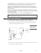
Operating Humidity • 5 - 95%, non-condensing WATCHDOG TIMER The Watchdog Timer is provided to ensure that standalone systems can recover from catastrophic conditions that cause the CPU to crash. This condition can occur from external EMI or a software bug. When the CPU stops working correctly, hardware on the board will either perform a hardware reset (cold boot) or a Non-Maskable Interrupt (NMI) to bring the system back to a known state.
The E2KEY.OBJ provides two library functions for you to integrate your application with the E2KEY function. The read_e2key and write_e2key libraries are written and compiled in C language. To implement them, refer to the functions below: */unsigned int read_e2key(unsigned int address): This function will return the E2KEY data to a certain address. The address range is from 0 to 63. Return data is one word, 16 bits.
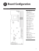
2 Board Configuration BOARD LAYOUT Figure 2. SBC-370 Configuration.
JUMPERS The default settings are highlighted in the tables that follow. CPU Frequency Setting (JP3) Frequency 1-3 2-4 3-5 4-6 50 MHz OFF OFF ON ON 66 MHz/100 MHz* ON ON OFF OFF 75 MHz OFF ON ON OFF 83.3 MHz ON OFF OFF ON *Intel Celeron CPU will auto-detect 66 MHz. * Intel Pentium III (FC-PGA) CPU will auto detect 100MHz. *Refer to figure 2 for the location of JP3. CPU Multiplier Setting (JP8) Ration 1-2 3-4 5-6 7-8 3.0 x ON OFF ON ON 3.5 x ON OFF OFF ON 4.
Watchdog Timeout Period (JP12) Period 1-2 3-4 5-6 7-8 1 sec. OFF OFF ON 2 sec. OFF OFF ON OFF ON 10 sec. OFF ON OFF OFF 20 sec. OFF ON OFF ON 110 sec. ON OFF OFF OFF 220 sec. ON OFF OFF ON Refer to figure 2 for the location of JP12. DiskOnChip™ Memory Address Setting (JP11) The DiskOnChip™ (DOC) Flash Disk Chip is produced by M-Systems. No extra software utility is needed because the DOC is 100% compatible to hard disk. It is "plug and play", easy, and reliable.
PS/2 Mouse Setting (JP7) The PS/2 mouse uses IRQ12 while in operation. JP7 Description ON Enable the PS/2 Mouse, IRQ12 OFF Disable the PS/2 Mouse Refer to figure 2 for the location of JP7.
CONNECTORS This section describes how to connect peripherals, switches, and indicators to the SBC-370. Floppy Disk Drive Connector (CN2) The SBC-370 is equipped with a 34-pin daisy-chain drive connector cable. For the location of this connector, refer to CN2 in figure 2.
PCI E-IDE Disk Drive Connector (CN1/CN3) You can attach four IDE (Integrated Device Electronics) hard disk drives to the SBC-370 IDE controller. • CN1 (IDE 1): Primary IDE Connector • CN3 (IDE 2): Secondary IDE Connector For the location of these connectors, refer to CN1 and CN3 in figure 2.
Parallel Port (CN4) This port is usually connected to a printer. The SBC-370 includes an onboard parallel port accessed through a 26-pin flat-cable connector. For the location of this connector, refer to CN4 in figure 2.
Serial Ports (CN12/CN11) The SBC-370 offers two high speed NS16C550 compatible UARTs with Read/Receive 16 byte FIFO serial ports (COM1/COM2).
Keyboard/Mouse Connector (CN8/CN17/CN18) The SBC-370 provides one external keyboard, one external mouse, and one PS/2 keyboard and mouse connector.
External Switches and Indicators (CN7) There are several external switches and indicators for monitoring and controlling the CPU board. All the functions are in the CN7 Multi Panel connector. For the location of this connector, refer to figure 2.
IrDA Infrared Interface Port (CN6) The built-in IrDA port supports Serial Infrared (SIR) or Amplitude Shift Keyed IR (ASKIR) interface. To use the IrDA port, configure the SIR or ASKIR model in the BIOS's Peripheral Setup's COM2. Then, the normal RS-232 COM2 will be disabled. For the location of this connector, refer to figure 2.
LAN RJ45 Connector (CN10) The SBC-370 is equipped with a built-in 10/100Mbps Ethernet Controller. You can connect it to your LAN through the RJ45 LAN connector. For the location of this connector, refer to figure 2. Pin Number Description 1 TX+ 2 3. 4. TXRX+ 75 W termination 5. 75 W termination 6. RX- 7. 75 W termination 8. 75 W termination LED Connector for LAN (CN5) For the location of this connector, refer to figure 2. Pin Number Description 1 VCC 2 LAN ACT.
SYSTEM INTERRUPTS (IRQS) IRQ Description IRQ0 System Timer IRQ1 Keyboard IRQ2 Cascade to IRQ Controller IRQ3 COM2/COM4 IRQ4 COM1/COM3 IRQ5 Unused IRQ6 Floppy Drive (FDC) IRQ7 Printer IRQ8 Real Time Clock IRQ9 Unused IRQ10 Unused IRQ11 Unused IRQ12 PS/2 Mouse IRQ13 FPU IRQ14 Primary IDE IRQ15 Secondary IDE DMA CHANNEL ASSIGNMENTS Channel Function 0 Available 1 Available 2 Floppy disk ( 8-bit transfer ) 3 Available 4 Cascade for DMA Controller 1 5 Available 6 A
1ST MB MEMORY ADDRESS MAP The default setting is highlighted.
3 AMI BIOS Setup Menus The SBC-370 uses the AMI PCI/ISA BIOS for system configuration. The AMI BIOS setup program is designed to provide maximum flexibility in configuring the system by offering various options for end user requirements. This section is provided to assist you in the proper usage of these features. GETTING STARTED When you turn the system on, the BIOS will enter the Power-On-Self-Test routines.
function is for Date/Time setting and Floppy/Hard Disk setting. Refer to the following screen. Date/Time: Use the left arrow, right arrow, and Enter keys to move from one field to the next. The numeric keys, 0-9, are used to change the field values. To set the date (MM:DD:YYYY), select one of the fields (Month, Day, or Year) and then press either PgUp or PgDn to set it to the current Month, Day, and Year. Follow the same procedure for setting the Time (HH/MM/SS).
The following screen will be displayed if you select Advanced CMOS Setup: You can change the value of each option by using the PgUp and PgDn key. The available options are shown on the right side of the screen. Quick Boot > : With the Quick Boot set to Enabled, the BIOS will only check the first 1 MB of the system memory, providing a quick boot when you turn on your computer. With the Quick Boot Disabled, the BIOS will test all system memory when it boots up.
Floppy Drive Swap >: This function enables you to swap the floppy disk drives through software without moving the hardware. Floppy Drive Seek >: When this option is Enabled, the BIOS will perform a Seek command on floppy drive A: before boot-up. PS/2 Mouse Support >: This is used to determine whether or not a PS/2 mouse is supported. System Keyboard >: Configures the keyboard. If you set it to Absent, the BIOS will not re- port keyboard errors.
ADVANCED CHIPSET SETUP These setup functions are working mostly for Chipset (Intel 440BX). These options are used to change the Chipset's registers. Carefully change any default setting, otherwise the system will run unstably. Configure SDRAM Timing by SPD >: Enabled will select predetermined optimal values of chipset parameters. When Disabled, chipset parameters return to setup information stored in CMOS.
PCI Frame Buffer USWC >: Used to specify whether or not a caching of the PCI VGA frame buffer is allowed. USWC Write Post >: Enable or disable the use of Uncacheable, Speculatable, Write-Com- bined memory. Graphics Aperture Size >: Define the size of Graphics Aperture. Search for MDA Resources >: Allows the BIOS to search for MDA resources when Yes is specified. 8bit I/O Recovery Time >: Define the length of time for 8 bit I/O recovery.
POWER MANAGEMENT SETUP Power Management/APM >: Enables or disables the Advanced Power Management feature. Green PC Monitor Power State >: Specify the power state of the monitor after the specified pe- riod of display-idle has ended. Video Power Down Mode >: Specify the power state of the VESA VGA video subsystem after the specified period of display-idle has ended. Hard Disk Power Down Mode >: Specify the power state of the hard disk after the specified pe- riod of hard drive-idle has ended.
PCI/PLUG AND PLAY SETUP This setup handles the SBC-370 PCI function. All PCI bus slots on the system use INTA#, thus all installed PCI slots must be set. Plug and Play Aware O/S >: When PNP OS is installed, interrupts will be reassigned by the OS when the setting is Yes. When a non-PNP OS is installed or to prevent reassigning of interrupt settings, set the setting to No. Clear NVRAM >: Specify whether or not the BIOS will clear NVRAM on every boot.
Offboard PCI IDE Card >: This function is used to specify whether or not an offboard PCI IDE card is installed in your computer. You must specify the slot number on the board which will be used for the card. Offboard PCI IDE Primary (/Secondary) IRQ >: Specify the PCI interrupt that is assigned to the Pri- mary (/Secondary) IDE channel on the offboard PCI IDE controller. PCI Slot (1,2,3,4) IRQ Priority >: Specify the IRQ priority to be used by the PCI devices on slots 1 to 4.
Serial Port B Mode >: Specify the mode of serial port 2. IR Duplex Mode >: Specify the mode of IR device that is connected to the IR port. IrDA Protocol >: Specify the function mode if an IrDA mode is selected. Onboard Parallel Port >: Specify the I/O port address of the parallel port. Parallel Port Mode >: Used to specify the mode of parallel port.
HARDWARE MONITOR SETUP There is a LM78 chip that can monitor onboard system voltage and fan speed. The voltage monitoring will cover +5V, +12V, -12V, and -5V. Note: Normal CPU fan RPM is more than 5000 RPM. If your CPU fan RPM is less than 5000 RPM, something is wrong and the CPU will be in overheat condition. Make sure that the connection at CN12/CN13 is correct.
CHANGE SUPERVISOR/USER PASSWORD Set a password that is used to protect your system and Setup Utility. Supervisor Password has higher priority than User Password. Once you setup the password, the system will ask you to enter the password every time you enter the BIOS SETUP. If you enter the BIOS SETUP with the Supervisor Password, you can access every setup option on the main menu.
AUTO CONFIGURATION WITH OPTIMAL SETTINGS This option lets you load the Optimal default settings. These settings are best-case values that will provide the best performance. Whenever your CMOS RAM is damaged, the Optimal settings will be loaded automatically.
AUTO CONFIGURATION WITH FAIL SAFE SETTINGS This option allows you to load the Fail Safe default settings when your computer cannot boot normally. These settings are not optimal, but are the most stable. SAVE SETTINGS AND EXIT Select this option when you finish setting all the parameters and want to save them into the CMOS. Simply press the Enter key and all the configuration changes will be saved.
Index A advanced chipset setup . . . . . . . . . advanced CMOS setup . . . . . . . . . allocate IRQ to PCI VGA . . . . . . . . ATX power supply, connecting . . . . . auto configuration with fail safe settings auto configuration with optimal settings auto-detect hard disk . . . . . . . . . . . . . . . . . . . . . . . . . . . . . . . . . . . . . . . . . . . . . . . . . . . . . . . . . . . 30 28 33 10 39 38 37 BIOS main setup menu . . . . . . . . . . . . advanced chipset setup . . . . . . . . . .
CPU multiplier setting . . . . . . . . DiskOnChip memory address setting. PS/2 mouse setting . . . . . . . . . . watchdog timeout period . . . . . . . watchdog timer type setting . . . . . jumpers . . . . . . . . . . . . . . . . . . . . . . . . . . . . . . . . . . . . . . . . . . . . . . . . . . . . . . 13 14 15 14 13 13 K keyboard connector . . . . . . . . . . . . . . . . . . 20 keyboard/mouse connector . . . . . . . . . . . . . . 20 L LAN RJ45 connector . . . . . . . . . . . . . . . . . .
139908(D) Xycom Automation, Inc. 734-429-4971 • Fax: 734-429-1010 http://www.xycom.