Intel® Server Chassis SC5400 User’s Guide A Guide for Technically Qualified Assemblers of Intel® Identified Subassemblies/ Products Intel Order Number D38435-005
Disclaimer Information in this document is provided in connection with Intel® products. No license, express or implied, by estoppel or otherwise, to any intellectual property rights is granted by this document.
Safety Information Important Safety Instructions Read all caution and safety statements in this document before performing any of the instructions. See also Intel Server Boards and Server Chassis Safety Information on the Intel® Server Deployment Toolkit CD and/or at http://support.intel.com/support/ motherboards/server/sb/cs-010770.htm. Wichtige Sicherheitshinweise Lesen Sie zunächst sämtliche Warnund Sicherheitshinweise in diesem Dokument, bevor Sie eine der Anweisungen ausführen.
重要安全指导 Warnings Heed safety instructions: Before working with your server product, whether you are using this guide or any other resource as a reference, pay close attention to the safety instructions. You must adhere to the assembly instructions in this guide to ensure and maintain compliance with existing product certifications and approvals. Use only the described, regulated components specified in this guide.
Installing or removing jumpers: A jumper is a small plastic encased conductor that slips over two jumper pins. Some jumpers have a small tab on top that you can grip with your fingertips or with a pair of fine needle nosed pliers. If your jumpers do not have such a tab, take care when using needle nosed pliers to remove or install a jumper; grip the narrow sides of the jumper with the pliers, never the wide sides.
vi Intel® Server Chassis SC5400 User’s Guide
Preface About this Manual Thank you for purchasing and using the Intel® Server Chassis SC5400. This manual is written for system technicians who are responsible for troubleshooting, upgrading, and repairing this server chassis. This document provides a brief overview of the features of the chassis, a list of accessories or other components you may need, troubleshooting information, and instructions on how to add and replace components on the Intel® Server Chassis SC5400.
Product Contents, Order Options, and Accessories This server chassis is compatible with the following Intel® Server Boards: • Intel® Server Board S5000PSL • Intel® Server Board S5000XVN Your Intel® Server Chassis SC5400 ships with the following items: • 670W or 830W power supply, installed in the chassis • A box of hardware components, referred to below as the "chassis hardware box" • Fan cables, installed in the Intel® Server Chassis SC5400 with product code SC5400LX or SC5400LXi • • • • • Chassis intr
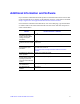
Additional Information and Software If you need more information about this product or information about the accessories that can be used with this server chassis, use the following resources. These files are available at http://support.intel.com/support/motherboards/server/chassis/SC5400/. Unless otherwise indicated in the table below, once on this Web page, type the document or software name in the search field at the left side of the screen and select the option to search "This Product.
x Intel® Server Chassis SC5400 User’s Guide
Contents Safety Information ..................................................................................................... iii Important Safety Instructions ........................................................................................ iii Wichtige Sicherheitshinweise ....................................................................................... iii Consignes de sécurité ..................................................................................................
SC5400LXi Only) ............................................................................................. 24 Removing Hot Swap Fans ...................................................................................... 24 Installing Hot Swap Fans ........................................................................................ 25 Installing and Removing a Slimline USB Floppy/CD/DVD Combo Kit ........................ 26 Installing a Slimline USB Floppy/CD/DVD Slimline Kit .........................
Product Regulatory Compliance ..................................................................................71 Product Safety Compliance ....................................................................................71 Product Regulatory Compliance References ..........................................................72 Electromagnetic Compatibility Notices ........................................................................75 FCC Verification Statement (USA) ....................................
Elektrostatische Entladungen (ESD) ...................................................................... 97 Andere Gefahren .................................................................................................... 98 Français ...................................................................................................................... 99 Consignes de sécurité sur le serveur .....................................................................
List of Figures Figure 1. Intel® Server Chassis SC5400 ................................................................................... 1 Figure 2. Internal Component Locations ................................................................................... 6 Figure 3. Front Control Panel .................................................................................................... 7 Figure 4. Intel® Local Control Panel Features....................................................................
Figure 43. Installing Plastic Air Baffle in Drive Carrier ............................................................ Figure 44. Inserting Drive Carrier into Hot Swap Cage........................................................... Figure 45. Removing Drive Carrier from Hot Swap Cage....................................................... Figure 46. Removing Plastic Air Baffle ................................................................................... Figure 47. Securing Hard Drive to Drive Carrier .
List of Tables Table 1. Server Chassis Features (BASE SKU) ....................................................................... 2 Table 2. Server Chassis Features (BRP SKU) .......................................................................... 3 Table 3. Server Chassis Features (LX SKU) ............................................................................. 4 Table 4. Server Chassis Features (LXi SKU) ............................................................................5 Table 5.
xviii Intel® Server Chassis SC5400 User’s Guide
1 Server Chassis Features This chapter briefly describes the main features of the Intel® Server Chassis SC5400. This chapter provides a list of the server chassis features, as well as diagrams showing the location of important components and connections on the server chassis. AF000551 Figure 1.
Table 1 summarizes the features of the Intel® Server Chassis SC5400 Base SKU Table 1. Server Chassis Features (BASE SKU) Feature Dimensions Hard Drives Description • • • • 16.6 inches high (Pedestal: 17 inches) 8.6 inches wide 27.4 inches deep (Pedestal: 28.4 inches) 34.6 kilograms One fixed drive bay for up to six fixed SAS or SATA drives. Optional hot-swap drive bays: • • Six-drive SAS/SATA Four-drive SAS/SATA An optional four-drive fixed drive bay is also available.
Table 2 summarizes the features of the BRP SKU. Table 2. Server Chassis Features (BRP SKU) Feature Dimensions Hard Drives Description • • • • 16.6 inches high (Pedestal: 17 inches) 8.6 inches wide 27.4 inches deep (Pedestal: 28.4 inches) 36.2 kilograms One fixed drive bay for up to six fixed SAS or SATA drives. Optional hot swap drive bays: • • Six-drive SAS/SATA Four-drive SAS/SATA An optional four-drive fixed drive bay is also available.
Table 3 summarizes the features of the LX SKU. Table 3. Server Chassis Features (LX SKU) Feature Dimensions Hard Drives Description • • • • 16.6 inches high (Pedestal: 17 inches) 8.6 inches wide 27.4 inches deep (Pedestal: 28.4 inches) 36.2 kilograms One fixed drive bay for up to six fixed SAS or SATA drives. Optional hot-swap drive bays: • • Six-drive SAS/SATA Four-drive SAS/SATA An optional four-drive fixed drive bay is also available.
Table 3 summarizes the features of the SC5400LXi SKU Table 4. Server Chassis Features (LXi SKU) Feature Dimensions Hard Drives Description • • • • 16.6 inches high (Pedestal: 17 inches) 8.6 inches wide 27.4 inches deep (Pedestal: 28.4 inches) 36.2 kilograms One fixed drive bay for up to six fixed SAS or SATA drives. Optional expanded or non-expanded hot-swap drive bays: • • Six-drive SAS/SATA Four-drive SAS/SATA An optional four-drive fixed drive bay is available.
Component Identification Internal Components A I H D E J B C K F G L AF000511 A. Fixed Power Supply G. Hard Disk Drive Cage Release Mechanisms (2) B. Rear Serial B Connector H. Front Panel Controls C. PCI Add-in Card Panel I. 5.25-inch Device Bays D. Memory Air Duct J. Front Panel USB/Serial B E. Processor Air Duct K. Fixed Drive Cage 4-Drive (accessory) F. Fixed Fans (2) L. Fixed Drive Cage 6-Drive Figure 2.
Front Control Panel The following figure shows the features available on the Front Control Panel. The Intel® Local Control Panel is optional. A B F C G D H E I TP00701 A. ID Toggle Switch F. NIC2 Activity LED (green) B. Reset Button G. ID LED (blue) C. NIC 1 Activity LED (green) H. Status LED (bi-color) D. Power Button I. NMI Button E. Hard Drive Activity LED (green) Figure 3.
Descriptions of the front control panel LEDs are listed in the following table. See your server documentation for functionality of buttons. Table 5. Front Control Panel LED Descriptions LED Name Power LED Status Green Condition Description On Power on Off Power off On System ready Blink System ready, but degraded: some CPU fault, DIMM killed Green/Blink Amber Blink Condition during BMC reset.
Intel® Local Control Panel The following figure shows the features available on the Intel® Local Control Panel. The Intel® Local Control Panel is optional. Note: The Intel® Local Control Panel requires the installation of the Intel® Remote Management Module. See your server board documentation to determine if this control panel is compatible with your server board. A B C D E AF000955 Callout Function A. LCD display (variable content) B. LCD up navigation button C. LCD down navigation button D.
Back Panel Features A G B F E D C TP00526 A. Fixed Power Supply B. I/O Ports C. PCI Add-in Card Slots D. PCI Card Latch E. Rear Serial B Connector (optional) F. Knockout G. AC Power Connector Note: I/O connectors vary, depending on the server board installed. See your server board documentation for port identification. Figure 5.
Peripheral Devices The chassis provides locations and hardware for installing hard drives, a floppy drive, a CD-ROM drive, or a DVD-ROM drive. The drives must be purchased separately. The following figure shows the available options. A B C AF000552 A. B. C. Slimline floppy drive / DVD-ROM drive / CD-ROM drive USB ports (2) Hard drive bays Figure 6.
Standard and Optional Hot-swap Drive Bays One bay supporting six cabled drives ships with the standard chassis. Optional hot swap drive bays may replace the six-drive fixed drive bay. An optional four-drive fixed drive bay (for cabled drives) is available. No tools are required to replace the fixed drive bays. Optional four-drive and six-drive SAS/SATA and SCSI hot-swap drive bays are available. For instructions on installing hard drives, see “Removing and Installing Hot Swap Drive(s)” on page 42.
Intel® Remote Management Module The Intel® Remote Management Module is available to provide advanced system management features. For installation instructions on installing the Intel® Remote Management Module, see the instructions provided with the module. Note: Some server boards may not support the Intel® Remote Management Module. See your server board documentation to determine if this feature is compatible with your server board.
14 Intel® Server Chassis SC5400 User’s Guide
2 Hardware Installations and Upgrades Before You Begin Before working with your server product, pay close attention to the “Safety Information” on page iii. This document provides instructions for adding and replacing chassis components. For instructions on replacing components on the server board, such as the processor and memory DIMMs, see the instructions provided with the server board.
Removing and Installing the Chassis Cover Removing the Chassis Cover The Intel® Server Chassis SC5400 must be operated with the top cover in place to ensure proper cooling. You will need to remove the top cover to add or replace components inside of the platform. Before removing the top cover, power down the server and unplug all peripheral devices and the AC power cable. Note: A non-skid surface or a stop behind the chassis may be needed to prevent the chassis from sliding on your work surface. 1.
Installing the Chassis Cover 1. Slide the chassis cover on the chassis. 2. Latch the cover securely to the chassis. 3. If the chassis will be re-shipped, secure the chassis cover to the chassis with the access cover screw (see letter “A” in the following figure). A A AF000572 Figure 8.
Removing and Installing the Front Bezel Removing the Bezel Assembly (Pedestal Only) Caution: Do not rotate the bezel assembly more than 40 degrees or you will damage the bezel assembly. Note: The bezel assembly consists of two components, a front door and a sub-bezel. 1. Observe the safety and ESD precautions at the beginning of this book. 2. Power down the server and unplug all peripheral devices and the AC power cable. 3. Remove the chassis cover.
Installing the Front Bezel (Pedestal Only) Caution: This step applies to a pedestal configuration chassis only. For instructions on installing a bezel in a rack-mount configuration, refer to the Rack Conversion kit Installation Guide: Intel® Server Chassis SC5400. 1. Open the outer bezel door of the bezel assembly (see letter “A” in the following figure). 2. Remove the filler panels that correspond to installed devices (see letter “B”). 3. Close the outer bezel door (see letter “C”). 4.
Removing and Installing the Processor and Memory Air Ducts Always operate your server chassis with the processor and memory air ducts in place. The air ducts are required for proper airflow within the chassis. For instructions on adding or replacing a processor, first remove the processor and memory air ducts, and then see your server board user guide for instructions on processor installations and removals.
Installing the Processor and Memory Air Ducts 1. If your system has two processors, remove the inner plastic air baffle from the inside of the processor air duct (see letter “A” in the following figure). Caution: This step only applies to systems with two processors. If your server board has only one processor installed, leave the inner air baffle in place and proceed to step two. A AF000323 Figure 12. Removing Inner Plastic Air Baffle from Processor Air Duct 2. Install the processor air duct.
4. Rotate the memory air duct downward until the two small tabs (see letter “D”) engage and the memory air duct latch (see letter “E”) snaps into place. B A B A 1 D 2 C D E A E AF000325 Figure 13. Installing the Processor and Memory Air Ducts Caution: The processor air duct interlocks with the memory air duct in two places before latching into place. Note: Use care to avoid pinching the cables.
Replacing a Fixed Fan (Intel® Server Chassis SC5400Base SC5400BRP only) Note: This procedure applies only to the Intel® Server Chassis SC5400 BASE and Intel® Server Chassis SC5400BRP configurations. The Intel® Server Chassis SC5400LX and SC5400LXi ship with hot-swap fans. 1. Observe the safety and ESD precautions at the beginning of this book. 2. Power down the server and unplug all peripheral devices and the AC power cable. 3. Remove the chassis cover.
Removing and Installing Hot Swap Fans (Intel® Server Chassis SC5400LX or SC5400LXi Only) Removing Hot Swap Fans Note: This procedure applies only to the Intel® Server Chassis SC5400LX and SC5400LXi configurations. The Intel® Server Chassis SC5400 BASE and Intel® Server Chassis SC5400BRP configurations ship with fixed fans. The hot-swap fans from the Intel® Server Chassis SC5300LX cannot be used in the Intel® Server Chassis SC5400LX or SC5400LXi. 1.
Installing Hot Swap Fans Note: This procedure applies only to the Intel® Server Chassis SC5400LX or SC5400LXi configurations. The Intel® Server Chassis SC5400 BASE and Intel® Server Chassis SC5400BRP configurations ship with fixed fans. The hot-swap fans from the Intel® Server Chassis SC5300 LX cannot be used in the Intel® Server Chassis SC5400LX or SC5400LXi. 1. Observe the safety and ESD precautions at the beginning of this book. 2. Remove the chassis cover if not removed in a previous step.
Installing and Removing a Slimline USB Floppy/ CD/DVD Combo Kit Installing a Slimline USB Floppy/CD/DVD Slimline Kit Refer to the Slimline USB Floppy/CD-ROM/DVD-ROM Drive Kit Install Guide that shipped with your slimline combo kit for installation instructions. Removing a Slimline USB Floppy/CD/DVD Combo 1. Observe the safety and ESD precautions at the beginning of this book. 2. Power down the server and unplug all peripheral devices and the AC power cable. 3. Remove the chassis cover.
7. If not replacing with another drive, re-attach pair of slides to an EMI shield and reinsert EMI shield/slide assembly into chassis for proper airflow. AF000605 Figure 18. Re-inserting Empty EMI Shield/Slide Assembly into Chassis 8. Install the front bezel. For instructions, see “Removing and Installing the Front Bezel” on page 18. 9. Install the chassis cover. For instructions, see “Installing the Chassis Cover” on page 17. 10. Plug all peripheral devices and the AC power cable into the server. 11.
6. Remove the DVD/CD-ROM drive/slide assembly from the chassis by pressing in on the slide release latches (see letter “A” in the following figure). Remove the slides from the DVD or CD-ROM drive by pulling the slides away from the drive (see letter “B”). A gentle pull should release the slide from the side dimple on the drive. A B A B AF000575 7. If not replacing with another drive, re-attach pair of slides to an EMI shield and reinsert EMI shield/slide assembly into chassis for proper airflow.
Installing a DVD or CD-ROM Drive 1. Observe the safety and ESD precautions at the beginning of this book. 2. Power down the server and unplug all peripheral devices and the AC power cable. 3. Remove the chassis cover. For instructions, see “Removing the Chassis Cover” on page 16. 4. Remove the front bezel if it is installed. For instructions, see “Removing and Installing the Front Bezel” on page 18. 5.
7. Insert the drive/slide assembly into the upper device bay until the slides lock into place. 8. Connect power and data cables. 9. Install the front bezel. For instructions, see “Removing and Installing the Front Bezel” on page 18. 10. Install the chassis cover. For instructions, see “Installing the Chassis Cover” on page 17. 11. Plug all peripheral devices and the AC power cable into the server. 12. Power up the server. Removing and Installing Fixed Hard Drive(s) Removing Fixed Hard Drive(s) 1.
A B TP00906 Figure 22. Removing Six-drive Fixed Drive Cage from Chassis 8. Loosen the thumb screw (see letter “A” in the following figure). Open the upper door of the drive cage (see letter “B”). B A AF000579 Figure 23.
9. Open the lower door. AF000946 Figure 24. Opening Lower Door of Fixed Drive Cage 10. Remove the drive/slide assembly from the drive cage. AF000588 Figure 25.
11. Remove the device slides from hard drive. If not replacing hard drive, insert empty device slides into drive cage. AF000947 Figure 26. Inserting Empty Device Slides into Drive Cage 12. Close the lower door of drive cage. AF000948 Figure 27.
13. Close the upper door. AF000949 Figure 28. Closing Upper Door of Fixed Drive Cage 14. Tighten the captive screw. AF000586 Figure 29. Tightening Thumb Screw 15. Reinstall fixed hard drive into chassis. 16. If other hard drives remain in the drive cage, reconnect power and data cables. 17. Install the front bezel. For instructions, see “Removing and Installing the Front Bezel” on page 18. 18. Install the chassis cover. For instructions, see “Installing the Chassis Cover” on page 17. 19.
Installing Fixed Hard Drive(s) 1. Observe the safety and ESD precautions at the beginning of this book. 2. Power down the server and unplug all peripheral devices and the AC power cable. 3. Remove the chassis cover. For instructions, see “Removing the Chassis Cover” on page 16. 4. Remove the front bezel if it is installed. For instructions, see “Removing and Installing the Front Bezel” on page 18. 5.
6. Loosen the captive screw (see letter “A” in the following figure). Open the upper door (see letter “B”). B A AF000579 Figure 31. Unlocking and Opening Upper Door of Fixed Drive Cage 7. Open the lower door. AF000580 Figure 32.
8. Remove a pair of device slides from the drive cage. AF000581 Figure 33. Removing Slides from Drive Cage 9. Attach the device slides to the hard drive. This is a tool-less operation. Insert pins on device slides into mounting holes on hard drive. Press firmly to secure device slides to hard drive. Ensure that the metal tabs on the device slides are facing the front of the hard drive and facing towards each other. AF000582 Figure 34.
10. Insert the drive/slide assembly into the drive cage. Make sure the cable connector end of the hard drive faces towards the rear of the drive cage. AF000583 Figure 35. Inserting Drive/Slide Assembly into Drive Cage 11. Repeat above steps for installation of additional hard drives into the drive cage. 12. Close the lower door of drive cage. . AF000584 Figure 36.
13. Close the upper door of drive cage. AF000585 Figure 37. Closing Upper Door of Fixed Drive Cage 14. Tighten the captive screw. AF000586 Figure 38. Tightening Captive Screw 15. Re-install fixed drive cage into chassis. 16. Connect power and data cables to connectors on hard drive(s). 17. Install the front bezel. For instructions, see “Removing and Installing the Front Bezel” on page 18. 18. Install the chassis cover. For instructions, see “Installing the Chassis Cover” on page 17. 19.
Routing Power Cables to Fixed Drives P2 Power Cable Routing Chassis Primary Side View To Upper Device Bay To Server Board To 4-Drive Cage To 6-Drive Cage Cable Slot PCI Add-in card retainer detail AF000510 Figure 39. Routing Power Cables to Fixed Drives Route longest power cables to the 6-drive bay and shorter cables to the 4-drive bay and upper device bay. Power Cable Routing Guidelines: • P3, P4 and P5 power cables route to removable drives.
Routing Data Cables to Fixed Drives Note: Front panel, USB and one IDE cable are pre-routed by the factory. SAS or SATA cables are supplied with the server board and hot-swap drive accessory kits. No cables are supplied with the fixed drive bay kit. • Route SAS/SATA data cables through the chassis openings located near the bottom of the drive cage. • Connect data cables to the respective fixed drive and to the appropriate connector on the server board.
Removing and Installing Hot Swap Drive(s) Removing Hot Swap Drive(s) 1. Rotate the black lever downwards to unlatch the drive carrier. With the black lever open, remove the drive carrier from the drive cage. AF000593 Figure 41. Releasing Drive Carrier from Hot Swap Cage 2. Remove the four screws securing the hard drive to the drive carrier. Remove the hard drive from the drive carrier. AF000595 Figure 42.
3. If not replacing with another hard drive, re-install the plastic air baffle into the empty drive carrier. Secure the plastic air baffle to the drive carrier using the four screws that were formerly attached to the hard drive. Note: Plastic air baffles are necessary in all empty drive carriers to ensure proper airflow within the chassis. AF000950 Figure 43. Installing Plastic Air Baffle in Drive Carrier 4. With the black lever open, insert the drive carrier into the drive cage.
Installing Hot Swap Drive(s) 1. Press in on the green latch (see letter “A” in the following figure) at the end of the drive carrier to disengage it from the hot swap drive cage. 2. Pull out on the black lever (see letter “B”) to fully open the drive carrier. When the lever reaches a fully opened position, it will push the drive carrier out from the hot swap drive cage. Slide the drive carrier out of the drive cage (see letter “C”). A B C AF000589 Figure 45. Removing Drive Carrier from Hot Swap Cage 3.
AF000591 Figure 47. Securing Hard Drive to Drive Carrier 5. With the black lever open, insert the drive carrier into the drive cage. Once inserted, rotate the black lever upwards to latch the drive carrier into position. AF000592 Figure 48.
Open the back panel PCI add-in card retention device (see letter “B”) by pressing open from the inside of the chassis. A A B AF000600 Figure 49.
7. Firmly grab the PCI add-in board by its top edge or outer corners and remove from the expansion slot on the server board. Place the removed PCI add-in board in an anti-static protective wrapper. Close the back panel PCI add-in card retention device. 8. Remove additional PCI add-in boards as necessary. When done, reinstall the PCI add-in card retainer and close the PCI add-in card retention device(s). 9. Install the front bezel. For instructions, see “Removing and Installing the Front Bezel” on page 18.
5. Press in on the two plastic tabs (see letter “A” in the following figure) and remove the PCI add-in card retainer. Open the back panel PCI add-in card retention device (see letter “B”) by pressing open from the inside of the chassis. Remove the PCI slot shield (see letter “C”), if it has not already been removed, by pushing the shield out from the inside of the chassis A A B C AF000954 Figure 50. Preparing Chassis for Addition of PCI Add-in Board 6.
7. Hold the PCI add-in board by its top edge or upper corners. Firmly press the add-in board into an expansion slot on the server board (see letter “A” in the following figure). Close the back panel PCI add-in card retention device (see letter “B”). A B AF000599 Figure 51. Installing Add-in Board 8. Repeat steps 2-10 until all the PCI add-in cards are installed.
9. Reinstall the PCI Add-in Card Retainer. AF000600 Figure 52. Reinstalling PCI Add-in Card Retainer 10. Attach cables if necessary. 11. Install the front bezel. For instructions, see “Removing and Installing the Front Bezel” on page 18. 12. Install the chassis cover. For instructions, see “Installing the Chassis Cover” on page 17. 13. Plug all peripheral devices and the AC power cable into the server. 14. Power up the server.
Installing Additional Hot Swap Power Supply Module Caution: This step only applies to a chassis with redundant power supply capability. Do not perform this step if your chassis has a fixed power supply. 1. Remove screws (see letter “A” in the following figure). Remove the power supply filler panel (see letter “B”). A A B AF000602 Figure 53. Removing Power Supply Filler Panel 2. Insert the power supply module until it clicks into place.
Replacing a Hot Swap Power Supply Warning: Hazardous voltage, current, and energy levels are present inside the power supply. There are no user-serviceable parts inside it; servicing should be done by technically qualified personnel. 1. Remove the power cable from the defective hot swap power supply. 2. If present, remove shipping screw securing defective hot swap power supply to chassis (see letter “A” in the following figure).
Replacing a Fixed Power Supply Warning: Hazardous voltage, current, and energy levels are present inside the power supply. There are no user-serviceable parts inside it; servicing should be done by technically qualified personnel. 1. Observe the safety and ESD precautions at the beginning of this book. 2. Power down the server and unplug all peripheral devices and the AC power cable. 3. Remove the chassis cover. For instructions, see “Removing the Chassis Cover” on page 16. 4.
Replacing the Power Distribution Board Warning: Hazardous voltage, current, and energy levels are present inside the power supply. There are no user-serviceable parts inside it; servicing should be done by technically qualified personnel. 1. Observe the safety and ESD precautions at the beginning of this book. 2. Power down the server and unplug all peripheral devices and the AC power cable. 3. Remove the chassis cover. For instructions, see “Removing the Chassis Cover” on page 16. 4.
7. Remove screw (see letter “A” in the following figure) securing center divider to the power supply cage. Push center divider straight back (see letter “B”) to release tabs from chassis slots. Then, while holding the right edge of the center divider at a downward angle, disengage tabs from chassis wall by pushing center divider up and sideways (see letter “C”). Remove center divider from power supply cage (see letter “D”). A B C D TP00696 Figure 59.
8. Loosen thumb screw (see letter “A” in the following figure) securing the power distribution board to the chassis. Lift the power distribution board off of the standoffs (see letter “B”) and then remove it through the back of the power supply cage (see letter “C”). You may have to feed the power cables through the power supply cage while removing the power distribution board. B A C TP00698 Note: Cables on back of power distribution board not shown to clarify insertion process. Figure 60.
9. Insert new power distribution board into power supply cage (see letter “A” in the following figure). Try to route the power cables to the appropriate area at the time of insertion (see Steps 9 and 10 below). Position the power distribution board on the four standoffs inside the power supply cage. Push down on the power distribution board to securely attach it to the standoffs (see letter “B”). Tighten thumb screw (see letter “C”).
12. Reinstall center divider (see letter “A” in the following figure) and secure to chassis with one screw (see letter “B”). B A C TP00843 Figure 62. Re-installing Center Divider 13. Insert hot swap power supply(ies) into chassis. Replace shipping screw(s) (see letter “A” in the following figure) if shipping chassis to another location. A AF000603 Figure 63.
14. Re-install the memory and processor air ducts. For instructions, see “Installing the Processor and Memory Air Ducts” on page 21. 15. Re-install the chassis cover. For instructions, see “Installing the Chassis Cover” on page 17. 16. Plug all peripheral devices and the AC power cable into the server. 17. Power up the server. Replacing the Control Panel The steps for replacing the front control panel and the Intel® Local Control Panel are nearly identical.
Installing and/or Removing a Server Board Note: The server board you can install in your chassis depends upon the chassis model. To install or remove a server board, do the following: 1. Observe the safety and ESD precautions at the beginning of this book. 2. Power down the server and unplug all peripheral devices and the AC power cable. 3. Remove the chassis cover. For instructions, see “Removing the Chassis Cover” on page 16. 4. Remove the front bezel assembly if it is installed.
Connecting and Disconnecting Cables to or from Server Board Caution: Use caution when routing cables to ensure that cables do not obstruct fan airflow. 1. See your Intel® Server Board User Guide or Quick Start User’s Guide for cable connection locations. 2. If your server has a hot swap power supply, secure the cables (that route toward the server board) to the chassis. Connecting Cables to Server Board 1.
62 Intel® Server Chassis SC5400 User’s Guide
3 Technical Reference Power Supply Specifications 670-W Single Power Supply Input Voltages • 100-127V at 50/60 Hz; 12A max. • 200-240V at 50/60 Hz; 7A max. 670-W Single Power Supply Output Voltages The following table lists the total wattage available from the power subsystem for each voltage. Ensure that your loads do not exceed the combined total wattage of 670 Watts. For information about calculating the power usage for your configuration, see “Calculating Power Usage” on page 65. Table 6.
830-W Single Power Supply Output Voltages The following table lists the total wattage available from the power subsystem for each voltage. If you configure your system heavily, ensure that your loads do not exceed the combined total wattage of 800 Watts. For information about calculating the power usage for your configuration, see “Calculating Power Usage” on page 65. Table 7. 830-W Power Supply Output Capability Voltage Maximum Current +3.3 V 25 A +5.0 V 33 A +5 V Standby 3A +12.0 51 A -12.
Current Usage Calculating Power Usage The total combined wattage for your configuration must be less than the wattage rating for your power supply. Use the two worksheets in this section to calculate the total used by your configuration. For current and voltage requirements of add-in boards and peripherals, see your vendor documents. Worksheet, Calculating DC Power Usage Table 9. Power Usage Worksheet Current (maximum) at voltage level: Device +3.
Worksheet, Total Combined Power Used by the Server 3. From the previous worksheet, enter the total current for each column. 4. Multiply the voltage by the total current to get the total wattage for each voltage level. Add the total wattage for each voltage level to arrive at the total combined power usage for the power subsystem. Table 10. Power Usage Worksheet 2 Voltage level and total current (V X A = W) Total Watts for each voltage level (+3.
Appendix B: Regulatory and Compliance Information Product Regulatory Compliance Warning: To ensure regulatory compliance, you must adhere to the assembly instructions in this guide to ensure and maintain compliance with existing product certifications and approvals. Use only the described, regulated components specified in this guide.
Product Regulatory Compliance References The following table references Server Chassis Compliance and markings that may appear on the product. Markings below are typical markings however, may vary or be different based on how certification is obtained. Note: Certifications Emissions requirements are to Class A. Table 11.
Table 11.
Table 11.
Electromagnetic Compatibility Notices FCC Verification Statement (USA) This device complies with Part 15 of the FCC Rules. Operation is subject to the following two conditions: (1) this device may not cause harmful interference, and (2) this device must accept any interference received, including interference that may cause undesired operation. For questions related to the EMC performance of this product, contact: Intel Corporation 5200 N.E.
Industry Canada (ICES-003) Cet appareil numérique respecte les limites bruits radioélectriques applicables aux appareils numériques de Classe A prescrites dans la norme sur le matériel brouilleur: "Apparelis Numériques", NMB-003 édictee par le Ministre Canadian des Communications.
Korean Compliance (RRL) Following is the RRL certification information for Korea. English translation of the notice above: 1. Type of Equipment (Model Name): On License and Product 2. Certification No.: On RRL certificate. Obtain certificate from local Intel representative 3. Name of Certification Recipient: Intel Corporation 4. Date of Manufacturer: Refer to date code on product 5.
Table 12. Product Ecology Compliance Markings Compliance Regional Description California China Compliance Reference Marking Example Compliance Reference California Code of Regulations, Title 22, Division 4.5; Chapter 33: Best Management Practices for Perchlorate Materials. Special handling may apply. See www.dtsc.ca.gov/ hazardouswaste/perchlorate. This notice is required by California Code of Regulations, Title 22, Division 4.5; Chapter 33: Best Management Practices for Perchlorate Materials.
Compliance Regional Description Europe Compliance Reference European Directive 2002/95/EC - Compliance Reference Marking Example None Required. Restriction of Hazardous Substances (RoHS). Threshold limits and banned substances are noted below. Quantity limit of 0.1% by mass (1000 PPM) for: Lead, Mercury, Hexavalent Chromium, Polybrominated Biphenyls Diphenyl Ethers (PBB/PBDE) Quantity limit of 0.
Other Markings Table 13. Other Markings Compliance Description Compliance Reference Marking Example Compliance Reference Stand-by Power Stand-by Power Warnings Multiple Power Cords Multiple Power Cords Warnings English: Applied to product if more than one power cord is used. This unit has more than one power supply cord. To reduce the risk of electrical shock, disconnect (2) two power supply cords before servicing. Applied to product if stand-by power switch is used.
Compliance Description Ground Connection Compliance Reference Ground Connection Warnings Compliance Reference Marking Example Line1 : “WARNING:” Swedish on line2: “Apparaten skall anslutas till jordat uttag, när den ansluts till ett nätverk." Finnish on line 3: "Laite on liitettävä suojamaadoituskoskettimilla varustettuun pistorasiaan." English on line 4: "Connect only to a properly earth grounded outlet.
End-of-Life / Product Recycling Product recycling and end-of-life take-back systems and requirements vary by country. Contact the retailer or distributor of this product for information about product recycling and / or take-back.
Appendix E: Installation/Assembly Safety Instructions English The power supply in this product contains no user-serviceable parts. Refer servicing only to qualified personnel. Do not attempt to modify or use the supplied AC power cord if it is not the exact type required. A product with more than one power supply will have a separate AC power cord for each supply. The power button on the system does not turn off system AC power.
After you have completed the six SAFETY steps above, you can remove the system covers. To do this: 1. Unlock and remove the padlock from the back of the system if a padlock has been installed. 2. Remove and save all screws from the covers. 3. Remove the cover(s). For proper cooling and airflow, always reinstall the chassis covers before turning on the system. Operating the system without the covers in place can damage system parts. To install the covers: 1.
Deutsch Benutzer können am Netzgerät dieses Produkts keine Reparaturen vornehmen. Das Produkt enthält möglicherweise mehrere Netzgeräte. Wartungsarbeiten müssen von qualifizierten Technikern ausgeführt werden. Versuchen Sie nicht, das mitgelieferte Netzkabel zu ändern oder zu verwenden, wenn es sich nicht genau um den erforderlichen Typ handelt. Ein Produkt mit mehreren Netzgeräten hat für jedes Netzgerät ein eigenes Netzkabel.
SICHERHEISMASSNAHMEN: Immer wenn Sie die Gehäuseabdeckung abnehmen um an das Systeminnere zu gelangen, sollten Sie folgende Schritte beachten: 1. Schalten Sie alle an Ihr System angeschlossenen Peripheriegeräte aus. 2. Schalten Sie das System mit dem Hauptschalter aus. 3. Ziehen Sie den Stromanschlußstecker Ihres Systems aus der Steckdose. 4. Auf der Rückseite des Systems beschriften und ziehen Sie alle Anschlußkabel von den I/O Anschlüssen oder Ports ab. 5.
Das System wurde für den Betrieb in einer normalen Büroumgebung entwickelt.
Français Le bloc d'alimentation de ce produit ne contient aucune pièce pouvant être réparée par l'utilisateur. Ce produit peut contenir plus d'un bloc d'alimentation. Veuillez contacter un technicien qualifié en cas de problème. Ne pas essayer d'utiliser ni modifier le câble d'alimentation CA fourni, s'il ne correspond pas exactement au type requis.
Afin de permettre le refroidissement et l'aération du système, réinstallez toujours les panneaux du boîtier avant de mettre le système sous tension. Le fonctionnement du système en l'absence des panneaux risque d'endommager ses pièces. Pour installer les panneaux, procédez comme suit: 1. Assurez-vous de ne pas avoir oublié d'outils ou de pièces démontées dans le système. 2. Assurez-vous que les câbles, les cartes d'extension et les autres composants sont bien installés. 3.
Español El usuario debe abstenerse de manipular los componentes de la fuente de alimentación de este producto, cuya reparación debe dejarse exclusivamente en manos de personal técnico especializado. Puede que este producto disponga de más de una fuente de alimentación No intente modificar ni usar el cable de alimentación de corriente alterna, si no corresponde exactamente con el tipo requerido.
Para obtener un enfriamiento y un flujo de aire adecuados, reinstale siempre las tapas del chasis antes de poner en marcha el sistema. Si pone en funcionamiento el sistema sin las tapas bien colocadas puede dañar los componentes del sistema. Para instalar las tapas: 1. Asegúrese primero de no haber dejado herramientas o componentes sueltos dentro del sistema. 2. Compruebe que los cables, las placas adicionales y otros componentes se hayan instalado correctamente. 3.
Italiano Rivolgersi ad un tecnico specializzato per la riparazione dei componenti dell'alimentazione di questo prodotto. È possibile che il prodotto disponga di più fonti di alimentazione. Non modificare o utilizzare il cavo di alimentazione in c.a. fornito dal produttore, se non corrisponde esattamente al tipo richiesto. Ad ogni fonte di alimentazione corrisponde un cavo di alimentazione in c.a. separato L'interruttore attivato/disattivato nel pannello anteriore non interrompe l'alimentazione in c.a.
Per il giusto flusso dell'aria e raffreddamento del sistema, rimettere sempre le coperture del telaio prima di riaccendere il sistema. Operare il sistema senza le coperture al loro proprio posto potrebbe danneggiare i componenti del sistema. Per rimettere le coperture del telaio: 1. Controllare prima che non si siano lasciati degli attrezzi o dei componenti dentro il sistema. 2. Controllare che i cavi, dei supporti aggiuntivi ed altri componenti siano stati installati appropriatamente. 3.
128 Intel® Server Chassis SC5400 User’s Guide
Appendix D: Safety Information English Server Safety Information This document applies to Intel® server boards, Intel® server chassis (pedestal and rackmount) and installed peripherals. To reduce the risk of bodily injury, electrical shock, fire, and equipment damage, read this document and observe all warnings and precautions in this guide before installing or maintaining your Intel® server product.
Indicates hot components or surfaces. Indicates do not touch fan blades, may result in injury. Indicates to unplug all AC power cord(s) to disconnect AC power Please recycle battery Intended Application Uses This product was evaluated as Information Technology Equipment (ITE), which may be installed in offices, schools, computer rooms, and similar commercial type locations.
• To reduce the weight for easier handling, remove any easily detachable components. Power and Electrical Warnings Caution: The power button, indicated by the stand-by power marking, DOES NOT completely turn off the system AC power, 5V standby power is active whenever the system is plugged in. To remove power from system, you must unplug the AC power cord from the wall outlet. Your system may use more than one AC power cord. Make sure all AC power cords are unplugged.
System Access Warnings Caution: To avoid personal injury or property damage, the following safety instructions apply whenever accessing the inside of the product: • Turn off all peripheral devices connected to this product. • Turn off the system by pressing the power button to off. • Disconnect the AC power by unplugging all AC power cords from the system or wall outlet. • Disconnect all cables and telecommunication lines that are connected to the system.
Electrostatic Discharge (ESD) Caution: ESD can damage disk drives, boards, and other parts. We recommend that you perform all procedures at an ESD workstation. If one is not available, provide some ESD protection by wearing an antistatic wrist strap attached to chassis ground -- any unpainted metal surface -- on your server when handling parts. Always handle boards carefully. They can be extremely sensitive to ESD. Hold boards only by their edges.
Cooling and Airflow Caution: Carefully route cables as directed to minimize airflow blockage and cooling problems. For proper cooling and airflow, operate the system only with the chassis covers installed. Operating the system without the covers in place can damage system parts. To install the covers: • Check first to make sure you have not left loose tools or parts inside the system. • Check that cables, add-in boards, and other components are properly installed.
Deutsch Sicherheitshinweise für den Server Das vorliegende Dokument bezieht sich auf Intel® Serverplatinen, Intel® Servergehäuse (Standfuß und Rack) sowie installierte Peripheriegeräte. Es enthält Warnungen und Vorsichtsmaßnahmen zur Vermeidung von Gefahren durch Verletzung, Stromschlag, Feuer und Beschädigungen von Geräten. Lesen Sie diese Dokument daher sorgfältig, bevor Sie Ihr Intel® Serverprodukt installieren oder warten.
Weist darauf hin, daß das Anfassen des Gebläses zu Verletzungen führen kann. Bedeutet, alle Netzkabel abzuziehen und das Gerät von der Netzspannung zu trennen. Bereiten Sie bitte Batterie auf Zielbenutzer der Anwendung Dieses Produkt wurde in seiner Eigenschaft als IT-Gerät getestet, das in Büros, Schulen, Computerräumen und ähnlichen öffentlichen Räumlichkeiten installiert werden kann. Die Eignung dieses Produkts für andere Einsatzbereiche als IT (z. B.
• Entfernen Sie alle Komponenten, die sich leicht abnehmen lassen, um das Gewicht zu reduzieren und die Handhabung zu erleichtern. Warnungen zu Netzspannung und Elektrizität Vorsicht: Durch Betätigen der mit dem Standby-Symbol gekennzeichneten Netztaste wird das System NICHT vollständig vom Netz getrennt. Es sind weiterhin 5 V aktiv, solange das System eingesteckt ist. Um das System vollständig vom Strom zu trennen, muß das Netzkabel aus der Steckdose abgezogen werden.
Hinweis für Netzkabel Wenn kein Netzkabel mit dem Produkt geliefert wurde, kaufen Sie ein Kabel, das für die Vorsicht: Prüfen Sie zur Vermeidung von Stromschlag- oder Feuergefahr die mit dem Produkt zu verwendenden Netzkabel wie folgt: • Nehmen Sie keine Änderungen an einem Netzkabel vor, und benutzen sie es nicht, wenn es nicht genau in die geerdeten Netzsteckdosen paßt.
Einbauen von Hot-Plug-Komponenten sorgfältig vor, um nicht mit heißen Komponenten in Berührung zu kommen. Vorsicht: Berühren Sie nicht die rotierenden Lüfterflügel, um Verletzungen zu vermeiden. Falls Ihr System mit eine Lüfterabdeckung besitzt, darf es nicht ohne diese Abdeckung betrieben werden. Warnhinweise für Racks Das Geräte-Rack muß auf einer geeigneten, festen Unterlage verankert werden, um ein Umkippen zu vermeiden, wenn ein Server oder andere Geräte herausgezogen werden.
Andere Gefahren Batterieaustausch Vorsicht: Wird die Batterie unsachgemäß ausgetauscht, besteht Explosionsgefahr. Verwenden Sie als Ersatz nur die vom Gerätehersteller empfohlene Batterie. Beachten Sie bei der Entsorgung von Batterien die gültigen Bestimmungen. Versuchen Sie nicht, eine Batterie aufzuladen. Versuchen Sie nicht, eine Batterie zu öffnen oder sonstwie zu beschädigen.
Français Consignes de sécurité sur le serveur Ce document s’applique aux cartes serveur Intel®, au châssis de serveur Intel® (sur pieds et sur rack) et aux périphériques installés. Pour réduire les risques de dommages corporels, d’électrocution, d’incendie et de dommages matériels, lisez ce document et respectez tous les avertissements et précautions mentionnés dans ce guide avant d’installer ou de mettre à jour votre produit serveur Intel®.
Indique de débrancher tous les cordons d’alimentation secteur pour déconnecter l’alimentation. Veuillez réutiliser la batterie Domaines d’utilisation prévus Ce produit a été testé comme équipement informatique (ITE) et peut être installé dans des bureaux, des écoles, des salles informatiques et des endroits commerciaux similaires.
Alimentation et avertissements en matière d’électricité Attention: Le bouton d’alimentation, indiqué par le symbole de mise en veille, NE COUPE PAS complètement l’alimentation secteur du système car le courant de veille 5 V reste actif lorsque le système est sous tension. Pour couper l’alimentation du système, vous devez débrancher le cordon d’alimentation secteur de la prise murale. Votre système peut utiliser plusieurs cordons d’alimentation secteur.
Avertissements sur l’accès au système Attention: Pour éviter de vous blesser ou d’endommager votre équipement, les consignes de sécurité suivantes s’appliquent chaque fois que vous accédez à l’intérieur du produit: • Mettez hors tension tous les périphériques connectés à ce produit. • Éteignez le système en appuyant sur le bouton d’alimentation. • Déconnectez l’alimentation secteur en débranchant tous les cordons d’alimentation secteur du système ou de la prise murale.
Pour éviter tout risque d’électrocution, le rack et chaque élément de l’équipement installé dans le rack doivent être correctement reliés à la terre. Décharges électrostatiques (ESD) Attention: Les décharges électrostatiques (ESD) peuvent endommager les lecteurs de disque dur, les cartes et d’autres pièces. Il est fortement conseillé d’effectuer l’ensemble des procédures décrites à un poste de travail protégé contre les ESD.
Périphériques laser Attention: Pour éviter tout risque d’exposition aux rayonnements et/ou de dommage personnel: • N’ouvrez pas l’enceinte d’un périphérique laser. • Les périphériques laser ne sont pas réparables par l’utilisateur. • Retournez-les au fabricant en cas de problème.
Español Información de seguridad del servidor Este documento se aplica a las tarjetas de servidor de Intel®, las carcasas de servidor de Intel® (montaje en bastidor y en pedestal) y los dispositivos periféricos. Para reducir el riesgo de daños corporales, descargas eléctricas, fuego y en el equipo, lea este documento y preste atención a todos las advertencias y precauciones de esta guía antes de instalar o mantener el producto de servidor de Intel®.
Indica que es necesario desenchufar los cables de alimentación de CA para desconectar la alimentación de CA Recicle por favor la batería Aplicaciones y usos previstos Este producto ha sido evaluado como equipo de tecnología informática (ITE) que puede instalarse en oficinas, escuelas, salas de equipos informáticos o lugares de ámbito comercial similares.
Advertencias de alimentación y eléctricas Precaución: El botón de encendido, indicado con la marca del modo de reposo o stand-by, NO DESCONECTA completamente la alimentación de CA del sistema, ya que el modo de reposo de 5 V sigue activo mientras el sistema está enchufado. Para desconectar el sistema debe desenchufar el cable de alimentación de CA de la toma de la pared. Puede usar más de un cable de alimentación de CA con el sistema.
• Los cables de la fuente de alimentación deben estar conectados a los enchufes con una toma de tierra adecuada. Advertencias el acceso al sistema Precaución: Para evitar lesiones personales o daños en la propiedad, se aplican las siguientes instrucciones de seguridad siempre que se acceda al interior del producto: • Apague todos los dispositivos periféricos conectados a este producto. • Pulse el botón de alimentación para apagar el sistema.
Extraiga las piezas del equipo del bastidor de una a una. El usuario es el responsable de la instalación de un dispositivo de desconexión de la alimentación principal para toda la unidad del bastidor. El acceso a este dispositivo de desconexión deberá ser de fácil acceso y deberán incluirse indicaciones que lo identifiquen como el control de alimentación eléctrica de toda la unidad, no sólo de los servidores.
• Sujete las cubiertas a la carcasa siguiendo las instrucciones del producto. Periféricos o dispositivos láser Precaución: Para evitar el riesgo de la exposición a radiaciones o de daños personales: • No abra la caja de ningún periférico o dispositivo láser • Los periféricos o dispositivos láser no pueden ser reparados por el usuario • Haga que el fabricante los repare.
简体中文 服务器安全信息 本文档适用于 Intel® 服务器主板、Intel® 服务器机箱(基座和机架固定件)和已安装的外设。为减少人身伤害、电击、火 以及设备毁坏的危险,请在安装或维护 Intel® 服务器产品之前阅读本文档并遵循本指南中的所有警告和预防措施。 如果本文档中的信息与特定产品的随附信息或 Web 站点信息之间存在不一致,请以产品文档为准。 服务器须由合格的技术人员进行集成和维护。 必须遵守本指南的规定和服务器手册的装配指导,以确保符合现有的产品认证和 批。仅使用本指南中描述和规定的指定组件。使用其他产品 / 组件将使产品的 认证和其他管理审批无效,并可能导致产品不符合销售地的产品法规。 安全警告与注意事项 为避免人身伤害与财产损失,安装本产品之前,请阅读以下所有安全指导和信息 下面所列的安全符号可能在整个文档中使用并可能标注于产品和 / 或产品包装之上。 注意 表示如果无视此“? ? ? 项”? ? ? ? ? ? ? 轻微人身伤害或财产损失的危 警告 表示如果无视此“? ? ”? ? ? ? ? ? ? 严重人身伤害的危险。 表示如果无视所示信息,即存在潜在的危险。 表示如果不遵守安
预期应用使用 根据评估,本产品为信息技术设备 (ITE),可安装在办公室、学校、计算机房和类似的商业场所。本产品对于非 ITE 应用的其他产品种类和环境(如医疗、工业、住宅、报警系统和测试设备)的适用 性尚有待进一步的评估。 场地选择 本系统专为在典型办公环境运行而设计。请选择符合以下条件的地点: • • • • • • • 清洁、干燥,无气载微粒(而非一般的室内尘埃)。 通风良好,远离热源(包括直接日晒和散热器)。 远离振动源或物理震动。 与电气设备产生的强大电磁场隔离。 在易受闪电袭击的地区,我们建议将系统插入电涌抑制器并在闪电期间断开通信 线路与调制解调器之间的连接。 提供正确接地的墙壁插座。 提供足够的空间,以便拿取电源供应线,因为这是本产品的主要电源断开器。 设备操作规范 减少人身伤害或设备受损的危险: • • • 移举设备时遵守当地的职业健康与安全要求。 借助机械手段或其他合适的手段移举设备。 拆除一切易分离组件,以降低重量并方便操作。 电源与电气警告 注意事项 电源按钮(如待机电源标记所示)并不能完全关闭系统的交流电源,只要系统已接 通电源,就存在 5V 待机电源。要从系统切断电源,须
为避免电击,请在打开服务器之前,关闭服务器并断开服务器上连接的电源线、电 信系统、网络和调制解调器。 电源线警告 如果产品未提供交流电线,请购买一根您所在国家批准使用的交流电线。 注意事项 为避免电击或火灾危险,请按如下所述对产品所用的电源线进行检查: • • • • 若非所需的符合接地插座的确切类型,请勿尝试修改或使用交流电线 电源线须符合以下标准: ⎯ 电源线的电气额定值须大于产品上标注的电流额定值。 ⎯ 电源线须拥有适合插座的安全接地插头或触点。 电源线为交流电源的主要断开设备。插座须靠近设备并可随时断开。 电源线须插入所提供的拥有合适接地的插座。 系统使用警告 注意事项 为避免人身伤害或财产损失,无论何时检查产品内部,以下安全指导都适用: • • • • • • • • 关闭所有与本产品相连的外设。 按下电源按钮至关闭状态,关闭系统。 从系统或墙壁插座上拔下所有交流电线,断开交流电源。 断开与系统相连的所有线缆和通信线路。 卸除舱口盖时,保留所有螺钉及其他紧固件。完成产品内部检查之后,请 用螺钉或紧固件重新固定舱口盖。 请勿打开电源供应设备。电源供应设备内没有可维修部件。请与生产商联系 维
注意事项 为避免受伤,请勿触摸运转的风机叶片。如果系统的风机上配有防护装置,请勿卸 下风机防护装置运行系统。 机架固定件警告 设备的机架须固定在稳固的支座上,以防从中安装服务器或设备时倒塌。须按照机 架生产商提供的安装说明进行安装。 从下往上将设备安装在机架上,最重的设备安装在机架的最底层。 一次只从机架上安装一件设备。 您须负责安装整个机架装置的主要电源断开设备。此主要断开设备须随时可用,且 须标明为控制整个装置(而不仅限于服务器)的电源。 为避免潜在的电击危险,须对机架及其上所安装的每一件设备实行正确的安全接地 。 静电放电 (ESD) 注意事项 ESD 会损坏磁盘驱动器、主板及其他部件。我们建议您执行 ESD 工作站的所有步骤。如果没有 ESD 工作站,则采取一些静电放电保护措施,操作部件时,戴上与服务器上的机箱接地 或任何未喷漆金属表面连接的防静电腕带。 操作主板时始终保持小心。它们可能对 ESD 非常敏感。拿持主板时只接触边缘。从保护包装中或从服务器上取出主板后,请将 主板组件侧面朝上放置在无静电的接地表面上。请使用导电泡沫垫(若有),不要 使用主板包装。请勿将主板在任何表面上滑动。 114
其他危险 替换电池 注意事项 不正确替换电池可能导致爆炸危险。替换电池时,请只使用设备生产商推荐使用的 电池。 请按当地法规处置电池。 请勿对电池充电。 请勿拆卸、刺穿或以其他方式损坏电池。 冷却和气流 注意事项 按照说明小心布置线缆,尽量减少气流阻塞和冷却问题。 为保证适当的冷却和气流,运行系统时请确保机箱盖已安装。未安装机箱盖即运行 系统可能导致系统部件受损。安装机箱盖的步骤如下: • • • 首先检查并确保系统内没有遗留的未固定工具或部件。 检查线缆、内插板和其他组件已正确安装。 按产品说明安装机箱盖。 激光外设或激光设备 注意事项 为避免幅射暴露和 / 或人身伤害: • 请勿打开任何激光外设或激光设备的外壳 • 激光外设或激光设备为非用户维修设备 请与生产商联系维修事宜 Intel® Server Chassis SC5400 User’s Guide 115
116 Intel® Server Chassis SC5400 User’s Guide
Appendix C: Warranty Limited Warranty for Intel® Chassis Subassembly Products Intel warrants that the Products (defined herein as the Intel® chassis subassembly and all of its various components and software delivered with or as part of the Products) to be delivered hereunder, if properly used and installed, will be free from defects in material and workmanship and will substantially conform to Intel's publicly available specifications for a period of three (3) years after the date the Product was purchased
Extent of Limited Warranty Intel does not warrant that Products to be delivered hereunder, whether delivered standalone or integrated with other Products, including without limitation semiconductor components, will be free from design defects or errors known as "errata." Current characterized errata are available upon request.
In the event of any conflict between the English language version and any other translated version(s) of this Limited Warranty, the English language version shall control. How to Obtain Warranty Service To obtain warranty service for this Product, you may contact Intel or your authorized distributor. • North America and Latin America To obtain warranty repair for the product, please go to the following Web site to obtain instructions: http://support.intel.com/support/ motherboards/draform.
86 Intel® Server Chassis SC5400 User’s Guide
Appendix A: Getting Help World Wide Web http://support.intel.com/support/motherboards/server/SC5400. Telephone All calls are billed US $25.00 per incident, levied in local currency at the applicable credit card exchange rate plus applicable taxes. (Intel reserves the right to change the pricing for telephone support at any time without notice). Before calling, fill out an Intel® Server Issue Report Form, available from the Web at http://support.intel.com/support/motherboards/server/SC5400.
In Asia-Pacific Region Australia.... 1800 649931 Cambodia.. 63 2 636 9797 (via Philippines) China ......... 800 820 1100 (toll-free) .................... 8 621 33104691 (not toll-free) Hong Kong 852 2 844 4456 India........... 0006517 2 68303634 (manual toll-free. You need an IDD-equipped telephone) Indonesia ... 803 65 7249 Korea ......... 822 767 2595 Malaysia .... 1 800 80 1390 Myanmar... 63 2 636 9796 (via Philippines) New Zealand 0800 444 365 Pakistan.....
Colombia ... Contact AT&T USA at 01 800 911 0010. Once connected, dial 800 843 4481 Costa Rica . Contact AT&T USA at 0 800 0 114 114. Once connected, dial 800 843 4481 Ecuador (Andimate) .... Contact AT&T USA at 1 999 119. Once connected, dial 800 843 4481 (Pacifictel) ..... Contact AT&T USA at 1 800 225 528. Once connected, dial 800 843 4481 Guatemala. Contact AT&T USA at 99 99 190. Once connected, dial 800 843 4481 Mexico ....... Contact AT&T USA at 001 800 462 628 4240.
70 Intel® Server Chassis SC5400 User’s Guide