
User manual

Connections Intel® Server Board SDS2
Revision 1.2
Order Number: A85874-002
86
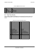
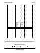
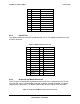
Keyboard Mouse
Pin Signal Name Pin Signal Name
1 KBDATA 1 MSDATA
2 N/C 2 N/C
3 GND 3 GND
4 Fused 5V 4 Fused 5V
5 KBCLK 5 MSCLK
6 N/C 6 N/C
8.7 Miscellaneous Headers
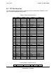
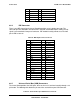
8.7.1 Fan Headers
There are two fan connectors for processors and four system fan connectors. All six fans are
monitored by the BMC and they all share the same pin-out.
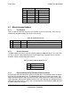
Table 74. Fan Header Pin-out
Pin Signal Name Type Description
1 GND Power GROUND is the power supply ground
2 12V Power Power Supply 12 V
3 Fan Tach Out FAN_TACH signal is connected to the BMC to monitor the FAN speed
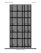
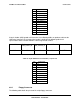
8.7.2 Chassis Intrusion
The BMC monitors the chassis intrusion switch by polling the ADM1026 device. The cable from
the chassis cover is connected through the 2-pin header below. To disable chassis intrusion
detection, short the 2-pin header with a jumper.
Table 75. Chassis Intrusion Header Pin-out
Pin Signal name
1 CHASSIS_INTR
2 GND
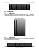
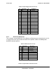
8.7.3 External SCSI Activity LED Input Signal Connector
A 4-pin header (labeled HDD LED at CN44) is provided on the Server Board to track SCSI drive
activity on the Hot Swap Back-plane. The following table details the pin-out of the header. This
allows two RAID controller cards to connect their disk activity cables to the front panel hard disk
LED activity light. Note that IDE hard disk activity LED is not enabled on the SDS2 board via the
front panel connector at CN37. Pins 2 and 3 are tied together routed through an AND gate to Pin
9 of CN37 front panel connector.