
User manual

Connections Intel® Server Board SDS2
Revision 1.2
Order Number: A85874-002
82
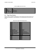
1 TXDP 7 RXDP
2 TXDM 8 RXDM
3 N/C 9 Activity LED Cathode
4 N/C 10 Link LED Anode
5 N/C 11 Speed LED Anode
6 N/C 12 3VSB
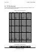
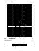
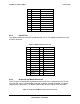
8.6.4 IDE Connector
There is one IDE channel on the Server Board through the use of a 40-pin connector. The
connector pin-out is detailed in the table below. Note IDE LED hard disk drive activity (Pin 39)
signal is not routed to the front panel connector. IDE hard disk activity will not cause the front
panel LED’s to turn on.
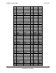
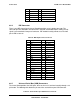
Table 66. IDE 40-pin Connector Pin-out
Pin Signal Name Pin Signal Name
1 RESET_L 2 GND
3 DD7 4 IDE_DD8
5 DD6 6 IDE_DD9
7 DD5 8 IDE_DD10
9 DD4 10 IDE_DD11
11 DD3 12 IDE_DD12
13 DD2 14 IDE_DD13
15 DD1 16 IDE_DD14
17 DD0 18 IDE_DD15
19 GND 20 KEY
21 IDE_DMARQ_L 22 GND
23 IDE_IOW_L 24 GND
25 IDE_IOR_L 26 GND
27 IDE_IORDY 28 GND
29 IDE_DMAACK_L 30 GND
31 IRQ_IDE 32 N/C
33 IDE_A1 34 N/C
35 IDE_A0 36 IDE_A2
37 IDE_DCS0_L 38 IDE_DCS1_L
39 IDE_HD_ACT_L 40 GND
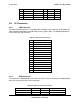
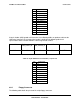
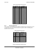
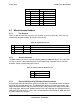
8.6.5 Universal Serial Bus (USB) Connectors
The Server Board provides four USB ports: three on the rear I/O and one internally through a 10-
pin header. The following table details the pin-out of the stacked three-port USB connector.
Table 67. Stacked Three-port USB Connector Pin-out