Intel® Server Board SHG2 Product Guide A Guide for Technically Qualified Assemblers of Intel® Identified Subassemblies/Products Order Number: A90327-002
Disclaimer Information in this document is provided in connection with Intel® products. No license, express or implied, by estoppel or otherwise, to any intellectual property rights is granted by this document.
Contents 1 Description Server Board Features ......................................................................................................... 9 Back Panel Connectors ............................................................................................. 10 Server Board Connector and Component Locations .................................................. 11 Processor .................................................................................................................. 12 Memory.....
3 Upgrading Tools and Supplies Needed................................................................................................ 43 Cautions ............................................................................................................................. 43 Memory .............................................................................................................................. 44 Processors .........................................................................................
Solving Problems Resetting the System ......................................................................................................... 79 Initial System Startup.......................................................................................................... 79 Checklist .................................................................................................................... 79 Running New Application Software.....................................................................
9 Equipment Log Worksheet Equipment Log ................................................................................................................... 95 Index ...................................................................................................................................... 97 Figures 1. 2. 3. 4. 5. 6. 7. 8. 9. 10. 11. 12. 13. 14. 15. 16. 17. 18. 19. 20. 21. 22. 23. 24. 25. 26. 27. 28. 29. 30. 31. 32. 33. 34. 35. 36. 37. vi Back Panel Connectors...................................
Tables 1. 2. 3. 4. 5. 6. 7. 8. 9. Contents Server Board Features .................................................................................................. 9 Video Modes ............................................................................................................... 13 Software Security Features ......................................................................................... 19 Configuration Utilities .........................................................................
viii Intel Server Board SHG2 Product Guide
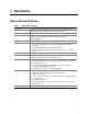
1 Description Server Board Features Table 1. Server Board Features Feature Description Processor Up to two 1.8 GHz to 2.4 GHz Intel® Xeon™ processors with 512K cache support packaged in a 603-pin micro Pin-Grid Array (PGA) System Bus Frequency 400 MHz Front Side Bus Memory (DRAM) Six 72-bit sockets for 184-pin, 200 MHz, 2.
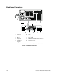
Back Panel Connectors A J B C K E NIC2 NIC1 (Gbit) (10/100) D F G H I OM14358 A AC Power* G Video B USB 1, 2, 3 H NIC2 (Gbit) C Mouse I NIC1 (10/100) D Keyboard J ICMB/External SCSI Connector Knockout* E Parallel Port K Serial B Knockout* F Serial A * Intel SC5200 Base chassis shown here. Item may be different on your chassis. Figure 1.
Server Board Connector and Component Locations II JJ KK LL HH A GG B FF CC C D E F G H I J K L M N O P EE DD BB AA Z Y Q X W V U T SR OM14357 A B C D E F G H I J K L M N O P Q R S Primary Processor Socket (CPU1) CPU2 Fan Secondary Processor Socket (CPU2) Front Panel USB Serial B Jumper Block CN27 System Fan 5 Floppy disk drive connector Secondary IDE System Fan 6 Primary IDE Front Panel connector IPMB Jumper Block CN43 System Fan 3 System Fan 4 HSBP B HSBP A HDD LED Connector T U V W X Y Z
Processor The Intel® Server Board SHG2 supports one or two Intel Xeon processors from 1.8 GHz to 2.4 GHz, with 512 KB of L2 advanced transfer cache packaged in a 603-pin micro-PGA (Pin-Grid Array). When two processors are installed, both processors must be identical. When only one processor is installed, the processor must be installed in the CPU1 socket, which is the socket closest to the corner of the server board. For a complete list of supported processors, see: http://support.intel.
Add-in Board Connectors The server board has the following add-in board connectors: • Two 184-pin full-length, 3.3 V, PCI-X 64-bit/100 MHz connectors. • Three 120-pin full-length, 5 V, standard PCI 32-bit/33 MHz connectors. • One 184-pin full-length, 3.3 V, connector that is capable if PCI-X 64-bit/133 MHz operation. To enable PCI-X 64-bit/133 MHz operation, you must disable the onboard SCSI controller using BIOS Setup. See page 57 for more information on using BIOS Setup.
SCSI Controller The embedded Adaptec AIC-7899W dual function SCSI controller provides Ultra160 (LVDS), (Ultra 2), and Ultra wide (SE) SCSI interfaces as two independent PCI functions. The Intel SHG2 baseboard provides active terminators, termination voltage, resetable fuse, and protection diode for both SCSI channels. Modular RAID Capable PCI-X Slot 6 The SHG2 server board supports a modular RAID controller, such as the Intel® RAID Controller SRCMR, on PCI-X Slot 6.
Network Controllers The server board includes two integrated onboard Network Interface Controllers (NICs). One NIC is a 10BASE-T/100BASE-TX network solution based on the Intel 82550PM single-chip Fast Ethernet PCI Bus Controller. As a PCI bus master, the controller can burst data at up to 132 MB/s. The controller contains two receive and transmit FIFO buffers that prevent data overruns or underruns while waiting for access to the PCI bus.
Adapter Fault Tolerance Adapter Fault Tolerance (AFT) is a simple, effective, and fail-safe approach to increase the reliability of server connections. AFT gives you the ability to set up link recovery to the server adapter in case of a cable, port, or network interface card failure. By assigning two server adapters as a team, AFT enables you to maintain uninterrupted network performance. AFT is implemented with two server adapters: a primary adapter and a backup, or secondary, adapter.
Keyboard and Mouse The keyboard/mouse controller is PS/2-compatible. If specified through the System Setup Utility (SSU), the server may be locked automatically if there is no keyboard or mouse activity for a predefined length of time. Once the inactivity (lockout) timer has expired, the keyboard and mouse do not respond until the previously stored password is entered. ACPI The SHG2 supports the Advanced Configuration and Power Interface (ACPI) as defined by the ACPI 1.0b.
Software Locks The BIOS Setup and the System Setup Utility (SSU) provide a number of security features to prevent unauthorized or accidental access to the system. Once the security measures are enabled, you can access the system only after you enter the correct password(s). For example: • • • • • • • Enable the keyboard lockout timer so that the server requires a password to reactivate the keyboard and mouse after a specified time-out period - 1 to 120 minutes. Set and enable a supervisor password.
Secure Mode Configure and enable the secure boot mode by using the SSU. When secure mode is in effect: • You can boot the server and the operating system will run, but you must enter the user password to use the keyboard or mouse. • You cannot turn off system power or reset the server from the front panel switches. Secure mode has no effect on functions enabled via the Server Manager Module or power control via the real time clock.
Table 3. Software Security Features (continued) Feature Description Set a time-out period so that keyboard and mouse input are not accepted Specify and enable an inactivity time-out period of from 1 to 120 minutes. Also, screen can be blanked, and writes to diskette can be inhibited If no keyboard or mouse action occurs for the specified period, attempted keyboard and mouse input will not be accepted.
2 Server Board Installation Tools and Supplies Needed • • • Phillips† (cross head) screwdriver (#1 bit and #2 bit) Flat blade screwdriver Antistatic wrist strap and conductive foam pad (recommended) Before You Begin Emissions Disclaimer To ensure EMC compliance with your local regional rules and regulations, the final configuration of your end system product may require additional EMC compliance testing. For more information, please contact your local Intel Representative.
Safety and Regulatory Compliance See “Regulatory and Integration Information” on page 91 for product Safety and EMC regulatory compliance information. Intended uses: This product was evaluated for use in servers that will be installed in offices, computer rooms, and similar locations. Other uses require further evaluation.
Installation Notes Installation Process Quick Reference Step Where the information is located Install the primary processor This guide Install the secondary processor (optional) This guide Install memory This guide Remove the access cover Your chassis manual Install the I/O shield This guide Rearrange the standoffs This guide Install the server board This guide Connect cables to the server board This guide and your chassis manual Finish setting up your chassis Your chassis manual Install
Attaching the Gasket to the I/O Shield 1. Remove the two backing strips from the gasket. 2. Press the gasket onto the inside face of the I/O shield as shown. OM14359 Figure 3. Attaching the Gasket to the I/O Shield Attaching the Label to the I/O Shield 1. Remove the backing from the label included with your server board. 2. Press the label onto the outside face of the I/O shield. US B 1 2 3 MO US E KY BD PA RA LL EL NIC 2 b (G it) N (10/ IC1 100) OM14360 Figure 4.
Installing the I/O Shield 1. Position one edge so that the dotted groove is outside the chassis wall, and the lip of the shield rests on the inner chassis wall. 2. Hold the shield in place, and push it into the opening until it is seated. Make sure the I/O shield snaps into place all the way around. OM14361 Figure 5.
Installing Memory The SHG2 Server Board contains six 184-pin DIMM sockets. Memory is partitioned as three banks. DIMMs must be populated in identical pairs. 2B 2A 3B 3A 1B 1A OM14558 Figure 6. DIMM Locations The SHG2 server board supports up to six 2.5 V, ECC, DDR 200 or 266-compliant, registered SDRAM 184-pin gold DIMMs. A wide range of DIMM sizes are supported, including 128 MB, 256 MB, 512 MB, 1 GB, and 2 GB DIMMs.
1. If the server board is not already installed in the chassis, remove the server board from its packaging and place it on a clean ESD protected work surface such as the antistatic plastic packaging in which the board was shipped. 2. Open both DIMM socket levers. 3. Insert DIMM making sure the connector edge of the DIMM aligns correctly with the slot. 4. Check that socket levers are securely latched. DIMMs must be populated in identical pairs. 2 1A 3 1 1B OM13205 Figure 7.
Installing the Server Board 1. Place the board into the chassis, making sure that the back panel I/O shield openings and chassis standoffs align correctly. 2. Attach the board with the screws included with your chassis at the ten locations marked below. For the Intel SC5200 chassis, these screws are packaged in a bag labeled “C.” 1 2 OM14363 Figure 9.
Installing the Processor(s) CAUTIONS If only one processor is to be used, it must be installed in the Processor Socket labeled CPU1, which is the socket closest to the corner of the server board. If you are adding a second processor to your system, you must verify that the second processor is identical in speed to the first processor. This server board has “zero-insertion-force” sockets.
3. Lift the socket lever on the processor socket labeled CPU1. (If adding a second processor, lift the socket lever on the processor socket labeled CPU2.) 4. Align the pins of the processor with the socket, and insert the processor into the socket. Lower the socket lever completely. ✏ NOTE When installing a second processor, note that the secondary processor socket is oriented so that the processor pins are rotated 180° relative to the primary processor socket. A B OM14365 A. B.
5. Apply thermal grease to the processor as shown. OM14366 Figure 12. Applying Thermal Grease 6. Align the heat sink with the retention brackets and place heat sink on the processor. OM14367 Figure 13.
7. Position the retention clip over the plastic tab and engage the retention clip end-slot over the plastic tab (see 1 in Figure 14). Note that the slot in the clip provides room for side-to-side motion while engaging the retention clip slots located at each end. 8. Press downward on the retention clip ends over the plastic tabs on the retention bracket (see 2 in Figure 14). 9. Install two retention clips for each processor you install. 2 1 2 OM14368 Figure 14.
1. Install processor wind tunnel center section over the heat sink / processor assembly. Note that plastic tabs on the wind tunnel center section engage the tabs on the retention clips. OM14369 Figure 16. Attaching the Wind Tunnel Assembly 2. Attach the processor wind tunnel fan to the wind tunnel air intake assembly as shown. The fan label must be pointing into the air intake assembly. Fan label OM14370 Figure 17.
3. Attach the air intake fan assembly to the side of the heat sink wind tunnel closest to the front of the chassis. a. Press both sides of the air intake section to bend tabs inward (see 1 in Figure 18). b. Insert tabs into slots on the wind tunnel center section (see 2 in Figure 18). c. Press the air intake section downward to engage the assembly (see 3 in Figure 18). 1 2 3 1 OM14371 Figure 18. Attaching the Wind Tunnel Intake and Exhaust 4.
Making Connections to the Server Board II JJ KK LL HH A GG B FF CC C D E F G H I J K L M N O P EE DD BB AA Z Y Q X W V U T SR OM14357 A. B. C. D. E. F. G. H. I. J. K. L. M. N. O. P. Q. R. S. Primary Processor Socket (CPU1) CPU2 Fan Secondary Processor Socket (CPU2) Front Panel USB Serial B Jumper Block CN27 System Fan 5 Floppy disk drive connector Secondary IDE System Fan 6 Primary IDE Front Panel connector IPMB Jumper Block CN43 System Fan 3 System Fan 4 HSBP B HSBP A HDD LED T.
Intel® SC5200 Base Server Chassis Note Connect front system fans to the System Fan 3 and System Fan 4 connectors on the server board. Intel SC5200 Hot-Swap, Redundant Power Server Chassis Note Be sure to attach system fans to their correspondingly numbered connector on the server board. System fan numbers can be found on the system fan carrier and on the system fan cables. Cable Routing – Intel SC5200 Base Chassis To ensure proper air-flow within the chassis, follow the cable routing guidelines below.
Floppy and Front Panel Cables Route the floppy drive and front panel cables as shown. A B OM14376 A. B. Front Panel Cable Floppy Diskette Cable Figure 22. Routing the Floppy and Front Panel Cables Cable Routing – Intel SC5200 Hot-Swap, Redundant Power Chassis Route the floppy drive cable and the hot-swap drive bay ICMB cable between the chassis wall and the hot-swap fan holder as shown below at location A. A OM14377 A. Cable Routing Location Figure 23.
Installing the Serial B Cable For the Intel SC5200 chassis, you can connect the Serial B serial port cable to either the front (rack configuration only) or back panels. Connecting it to the back panel is illustrated below. 1. Install the Serial B cable by inserting it into the chassis back panel cutout and attaching it as shown. 2. Attach the other end to the Serial B connector located on your server baseboard. See “Making Connections to the Server Board” on page 35 for the Serial B connector location.
Finishing Up WARNING An electrical shock hazard exists if the chassis cover is not replaced before connecting the chassis AC power. 1. 2. 3. 4. Install the chassis cover according to the instructions for your chassis. See your chassis documentation to complete rack or pedestal installation. Connect the keyboard, mouse and monitor cables to the back panel. Connect the power cable to the back panel and to an AC outlet.
Getting Started with Intel® Server Management and Intel® SMaRT Tool (Optional) Intel® Server Management and the hard drive Service Partition provide real-time monitoring and alerting for your SHG2 server hardware, emergency remote management, and remote server setup. Intel Server Management is implemented by installing it within client-server architecture. The Service Partition provides you with the ability to remotely access a local partition on the server and to identify and diagnose server health issues.
Installing your Operating System Install your operating system now. Installing Intel Server Management You can install Intel Server Management on a local server or on a remote workstation that is used to manage a LAN/WAN. 1. 2. 3. 4. 5. 6. Insert the Intel Server Management CD into the system’s CD-ROM. Click Install Server Management. Complete the Registration form and click Submit. Select the applicable system option. Review the Intel Software License Agreement and click Accept.
Installing Intel SMaRT Tool Follow the instructions below to install the Intel Server Maintenance and Reference Training Tool (SMaRT Tool) on your system. ✏ NOTES SMaRT Tool may only be installed on a system running a Microsoft Windows operating system. To download the SHG2 SC5200 server system module for SMaRT Tool, you must have Internet access. 1. Insert the Intel Server Board SHG2 Resource CD into the system’s CD-ROM drive. 2. Click on Intel SMaRT Tool in the menu on the left side of the screen. 3.
3 Upgrading Tools and Supplies Needed • • Phillips (cross head) screwdriver (#1 bit and #2 bit) Antistatic wrist strap and conductive foam pad (recommended) Cautions These warnings and cautions apply throughout this chapter. Only a technically qualified person should configure the server board. CAUTIONS System power on/off: The power button DOES NOT turn off the system AC power. To remove power from system, you must unplug the AC power cord from the wall outlet.
Installing or removing jumpers: A jumper is a small plastic encased conductor that slips over two jumper pins. Some jumpers have a small tab on top that you can grip with your fingertips or with a pair of fine needle nosed pliers. If your jumpers do not have such a tab, take care when using needle nosed pliers to remove or install a jumper; grip the narrow sides of the jumper with the pliers, never the wide sides.
1. Open both DIMM socket levers. 2. Insert DIMM making sure the connector edge of the DIMM aligns correctly with the slot. 3. Check that socket levers are securely latched. DIMMs must be populated in identical pairs. 2 1A 3 1 1B OM13205 Figure 26. Installing Memory Processors WARNING If the server has been running, any installed processor and heat sink on the processor board(s) will be hot.
Adding or Replacing a Processor If you are adding a second processor to your system, the second processor must be identical in speed with the first processor. 1. Observe the safety and ESD precautions at the beginning of this chapter and the additional cautions given here. 2. Remove power from your system by unplugging the AC power cord. 3. Remove the side cover (see your system or chassis documentation for instructions). 4.
5. Lift the socket lever on the processor socket labeled CPU1. (If adding a second processor, lift the socket lever on the processor socket labeled CPU2.) 6. Align the pins of the processor with the socket, and insert the processor into the socket. Lower the socket lever completely. ✏ NOTE When installing a second processor, note that the secondary processor socket is oriented so that the processor pins are rotated 180° relative to the primary processor socket. A B OM14365 C. D.
7. Apply thermal grease to the processor as shown. OM14366 Figure 29. Applying Thermal Grease 8. Align the heat sink with the retention brackets and place heat sink on the processor. OM14367 Figure 30.
9. Position the retention clip over the plastic tab and engage the retention clip end-slot over the plastic tab (see 1 in Figure 31). Note that the slot in the clip provides room for side-to-side motion while engaging the retention clip slots located at each end. 10. Press downward on the retention clip ends over the plastic tabs on the retention bracket (see 2 in Figure 31). 11. Install two retention clips on each processor you install. 2 1 2 OM14368 Figure 31.
2. Attach the processor wind tunnel fan to the wind tunnel air intake assembly as shown. The fan label must be pointing into the air intake assembly. Fan label OM14370 Figure 33. Attaching the Heat Sink Fan to the Air Intake Assembly CAUTION To ensure proper system cooling, the heat sink fan must be installed as shown in Figure 34 and the air intake fan assembly must be attached to the side of the processor / wind tunnel assembly nearest to the front of the chassis.
3. Attach the air intake fan assembly to the side of the heat sink wind tunnel closest to the front of the chassis. a. Press both sides of the air intake section to bend tabs inward (see 1 in Figure 34). b. Insert tabs into slots on the wind tunnel center section (see 2 in Figure 34). c. Press the air intake section downward to engage the assembly (see 3 in Figure 34). 1 2 3 1 OM14371 Figure 34. Attaching the Wind Tunnel Intake and Exhaust 4.
Removing a Processor 1. Observe the safety and ESD precautions at the beginning of this chapter and the additional cautions given here. 2. Unplug the heat sink fan. 3. Detach the processor wind tunnel, if attached to the heat sink. 4. Detach the heat sink clip from the processor socket. See the documentation that shipped with your processor for more detail. 5. Remove the heat sink from the processor. 6. Raise the locking bar on the socket. 7. Remove the processor from the socket.
1. Observe the safety and ESD precautions at the beginning of this chapter. 2. Open the chassis. 3. Insert the tip of a small flat-blade screwdriver, or equivalent, under the tab in the plastic retainer. Gently push down on the screwdriver to lift the battery. 4. Remove the battery from its socket. 5. Dispose of the battery according to local ordinance. 6. Remove the new lithium battery from its package, and, being careful to observe the correct polarity, insert it in the battery socket. 7.
Intel Server Board SHG2 Product Guide
4 Configuration Software and Utilities This chapter describes the Power-On Self-Test (POST) and server configuration utilities. The table below briefly describes the utilities. Table 4. Configuration Utilities Utility Description Page BIOS Setup Used for modifying server board set features, including setting time, date, and system passwords; setting the boot device priority; configuring the diskette drive and serial ports; and enabling the SCSI BIOS and system management features.
Power-On Self-Test (POST) Each time you turn on the system, POST starts running. POST checks the server board, processor, memory, keyboard, and most installed peripheral devices. During the memory test, POST displays the amount of memory that it is able to access and test. The length of time needed to test memory depends on the amount of memory installed. POST is stored in flash memory. 1. Turn on your video monitor and server. After a few seconds POST begins to run. 2.
Using BIOS Setup This section describes the BIOS Setup options. Use Setup to change the server configuration defaults. You can run Setup with or without an operating system being present. Setup stores most of the configuration values in battery backed CMOS; the rest of the values are stored in flash memory. The values take effect when you boot the server. POST uses these values to configure the hardware; if the values and the actual hardware do not agree, POST generates an error message.
Using the System Setup Utility The System Setup Utility (SSU) is located on the Intel Server Board SHG2 Resource CD-ROM shipped with the server.
Running the SSU When the SSU starts in the default local execution mode, the SSU accepts input from the keyboard or mouse. The SSU presents a VGA-based GUI on the primary monitor. If you run the SSU from read-only media, such as the CD-ROM, you cannot save user preference settings (such as screen colors). The SSU supports ROM-DOS version 6.22. The SSU will not operate from a “DOS box” running under an operating system such as Windows. To start the SSU: 1.
Customizing the SSU Interface The SSU lets you customize your interface using the Preferences section of the main window. The SSU sets these preferences and saves them in the AF.INI file so that they take effect the next time you start the SSU. There are four user customizable settings: • • • • ✏ Color - lets you change the default colors associated with different items on the screen using predefined color combinations. The color changes take effect immediately.
Setting the Admin Password The Admin Password button lets you set or change the admin password used by both the SSU and the system BIOS. This option is not available if both an admin and a user password are set and you entered only the user password when you started the SSU. All changes to the admin password take effect immediately. To change or clear the administrator password: 1. From the SSU Main window, choose Security. 2. Click the Admin Password button. 3.
Viewing the System Event Log To view the System Event Log (SEL): 1. From the SSU Main window, choose SEL Manager. When you start the SEL Manager, it automatically loads the current list of events from non-volatile memory. 2. Use the and keys to scroll the window contents to the left and right to view all of the columns. 3. Use the File and SEL menu items to work with the SEL information: • Open: Views data from a previously saved SEL file.
Viewing Sensor Data Records To view the Sensor Data Records (SDR): 1. From the SSU Main window, choose SDR Manager. When you start the SDR Manager, it automatically loads the SDR entries from non-volatile memory. The SDR Manager window has a navigation pane on the left that displays, in a tree format, the sensor data records. The tree has categories for each type of record. Clicking on a category expands or collapses a list of SDRs for that category.
Updating the Firmware To update the system firmware: 1. Download the update from the Intel support website. 2. From the SSU Main window, choose System Update. (System Update is available only in Expert mode.) 3. When you start System Update, it automatically displays the current revision information for the system firmware and BIOS. 4. From the File menu, choose Load and choose a .uif or .hex file to use for the update. 5. Click the Update button to perform the update.
Restoring a Configuration To restore the system configuration from a file: 1. From the SSU Main window, choose Config Save/Restore. (Configuration Save/Restore is available only in Expert mode.) 2. Click Restore from File and specify a filename and location. The CSR reads the platform type, BIOS revision, and firmware revision from the file and compares that information with the same information retrieved from the server.
5. 6. 7. 8. 9. Click Save to save the changes. Click Close to return to the PEM window. In the PEM window, click Configure PEP. Select the Enable PEP check box. In the Blackout Period box, enter the minimum time, in minutes, between successive pages. The valid range is [0 - 255] where 0 disables the blackout period. Setting a blackout period can save you from being flooded with repeat pages. After you receive a PEP page, no additional pages are sent by PEP for the duration of the blackout period. 10.
7. If you chose Static IP Setup in the previous step, fill in the IP addressing boxes: • Host IP Address: the IP address of this server. • Gateway IP Address: the IP address of the router for this server. • Subnet Mask: the IP address for the server’s subnet. The server uses this to decide if the alert destination is on the same subnet. 8. In the Alert IP Address box, fill in the IP address of the system you want to receive alerts from this server.
• Restricted: a remote system can initiate a LAN connection, but cannot perform control operations such as power down, reset, or front panel NMI. • Disabled: remote systems are not allowed to initiate LAN connections. 5. In the IP Setup box, choose either: • DHCP: the IP address for the server is automatically assigned by the DHCP (dynamic host control protocol) server on the network. The Host, Gateway, and Subnet Mask boxes in the dialog are ignored.
8. From the Connection Mode list, choose either: • Direct Connect: the COM2 port on the server is connected by a serial cable to the remote system. • Modem Connect: the COM2 port on the server is connected to a modem. 9. Click Save to save the changes. 10. Click Close to return to the PEM window.
How You Use the FRUSDR Load Utility This utility is compatible with ROM-DOS Ver. 6.22, MS-DOS† Ver. 6.22, and later versions. The utility accepts CFG, SDR and FRU load files. The executable file for the utility is frusdr.exe. The utility requires the following supporting files: • • • One or more .fru files describing the system’s field replaceable units A .cfg file describing the system configuration A .
Displaying SM BIOS Area The SM BIOS area is displayed in ASCII format when the field is ASCII or as a number when the field is a number. Each SM BIOS area displayed is headed with the SM BIOS area designated name. Each field has a field name header followed by the field in ASCII or as a number. Displaying FRU Area The FRU area is displayed in ASCII format when the field is ASCII or as a number when the field is a number. Each FRU area displayed is headed with the FRU area designated name.
Updating the SDR Nonvolatile Storage Area After the utility validates the header area of the supplied SDR file, it updates the SDR repository area. Before programming, the utility clears the SDR repository area. The SDR file is loaded via the .cfg File. Then the utility filters all tagged SDRs depending on the product configuration set in the Configuration File. Nontagged SDRs are automatically programmed. The utility also copies all written SDRs to the SDR.TMP file.
Upgrading the BIOS Preparing for the Upgrade Before you upgrade the BIOS, prepare for the upgrade by recording the current BIOS settings, obtaining the upgrade utility, and making a copy of the current BIOS. Recording the Current BIOS Settings 1. Boot the computer and press when you see the message: Press to enter SETUP 2. Write down the current settings in the BIOS Setup program. ✏ NOTE Do not skip step 2. You will need these settings to configure your computer at the end of the procedure.
Creating the BIOS Upgrade Diskette The BIOS upgrade file is a compressed self-extracting archive that contains the files you need to upgrade the BIOS. 1. Insert the bootable diskette into the diskette drive. 2. Extract the contents of the BIOS.EXE file onto the bootable diskette. To do this, read the instructions distributed with the BIOS package. Upgrading the BIOS 1. Place the bootable diskette containing the BIOS update files into the diskette drive of your system.
Recovering the BIOS It is unlikely that anything will interrupt the BIOS upgrade; however, if an interruption occurs, the BIOS could be damaged. The following steps explain how to recover the BIOS if an upgrade fails. In the event of BIOS corruption, the following procedure may be used to perform a BIOS recovery boot. 1. Prepare a bootable floppy diskette containing the BIOS recovery files for the SHG2 server board obtained from Intel’s web sites. 2.
Using the Firmware Update Utility The Firmware Update Utility is a DOS-based program used to update the Baseboard Management Controller’s firmware code. You only need to run the Firmware Update Utility if new firmware code becomes necessary or the firmware becomes corrupted. It is highly recommended that you also update the FRU/SDR files at the same time that you update the BMC Firmware. You can obtain the latest version of the firmware update file from the Intel Customer Support website: http://support.
Recovering the BMC Firmware In the event of BMC Firmware corruption, the following procedure may be used to perform a BMC Firmware recovery boot. 1. Prepare a bootable floppy diskette containing the updated BMC firmware files for the SHG2 Server Board obtained from Intel’s Customer Support web site. 2. Power off the system, unplug the power cord, and remove the chassis cover. 3. Add a jumper on CN47 pins 1-2 (BMC Force Update). 4. Insert the BMC Firmware floppy diskette into the disk drive. 5.
Using the Adaptec SCSI Utility The Adaptec SCSI utility detects the SCSI host adapters on the server board. The utility runs out of BIOS and is used to: • Change default values • Check and/or change SCSI device settings that may conflict with those of other devices in the server Running the SCSI Utility 1. When this message appears on the video monitor: Press Ctrl-A to run SCSI Utility... 2. Press to run this utility. When it appears, choose the host adapter that you want to configure.
5 Solving Problems This chapter helps you identify and solve problems that might occur while you are using the system. Resetting the System To do this: Press: Soft boot reset, which clears system memory and reloads the operating system. Clear system memory, restart POST, and reload the operating system. Reset button Cold boot reset. Turn the system power off and then on. This clears system memory, restarts POST, reloads the operating system, and halts power to all peripherals.
Running New Application Software Problems that occur when you run new application software are usually related to the software. Faulty equipment is much less likely, especially if other software runs correctly. Checklist q Does the system meet the minimum hardware requirements for the software? See the software documentation. q Is the software an authorized copy? If not, get one; unauthorized copies often do not work.
More Problem Solving Procedures This section provides a more detailed approach to identifying a problem and locating its source. Preparing the System for Diagnostic Testing CAUTION Turn off devices before disconnecting cables: Before disconnecting any peripheral cables from the system, turn off the system and any external peripheral devices. Failure to do so can cause permanent damage to the system and/or the peripheral devices. 1. Turn off the system and all external peripheral devices.
Verifying Proper Operation of Key System Lights As POST determines the system configuration, it tests for the presence of each mass storage device installed in the system. As each device is checked, its activity light should turn on briefly. Check for the following: q Does the diskette drive activity light turn on briefly? If not, see “Diskette Drive Activity Light Does Not Light” on page 84.
No Characters Appear on Screen Check the following: q Is the keyboard functioning? Check to see that the “Num Lock” light is functioning. q Is the video monitor plugged in and turned on? q Are the brightness and contrast controls on the video monitor properly adjusted? q Are the video monitor switch settings correct? q Is the video monitor signal cable properly installed? q Is the onboard video controller enabled? If you are using an add-in video controller board, do the following: 1.
System Cooling Fans Do Not Rotate Properly If the system cooling fans are not operating properly, system components could be damaged.
CD-ROM Drive Activity Light Does Not Light Check the following: q Are the CD-ROM drive’s power and signal cables properly installed? q Are all relevant switches and jumpers on the drive set correctly? q Is the drive properly configured? q Is the onboard IDE controller enabled? Cannot Connect to a Server q Make sure you are using the drivers that are shipped on the system Configuration Software CD for the onboard network controller. q Make sure the driver is loaded and the protocols are bound.
PCI Installation Tips Some common PCI tips are listed here. q Certain drivers may require interrupts that are not shared with other PCI drivers. The SSU can be used to adjust the interrupt numbers for PCI devices. For certain drivers, it may be necessary to alter settings so that interrupts are not shared. Problems with Application Software If you have problems with application software, do the following: q Verify that the software is properly configured for the system.
6 Getting Help World Wide Web http://support.intel.com/support/motherboards/server/SHG2 Telephone All calls are billed US $25.00 per incident, levied in local currency at the applicable credit card exchange rate plus applicable taxes. In U.S.
Intel Server Board SHG2 Product Guide
7 Technical Reference Server Board Jumpers 1 3 2 4 CN27 11 9 7 5 3 1 4 3 2 1 CN43 12 10 8 6 4 2 CN53 OM14373 Figure 37. Jumper Locations Table 7. Configuration Jumper (CN43) Jumper Name Pins What it does at system reset CMOS clear 1-2 If these pins are jumpered, the CMOS settings will be cleared on the next reset. These pins should not be jumpered for normal operation. Password Clear 3-4 If these pins are jumpered, the password will be cleared on the next reset.
Table 8. Configuration Jumper (CN27) Jumper Name Pins What it does at system reset BIOS Write Protect 1-2 If these pins are jumpered, write protect is disabled allowing the BIOS boot block to be updated. This feature is used in the rare case that a BIOS update requires a BIOS boot block update as well. These pins should not be jumpered for normal operation. BMC Write Protect 3-4 If these pins are jumpered, write protect is disabled allowing the BMC boot block to be updated.
8 Regulatory and Integration Information Product Regulatory Compliance Product Safety Compliance The SHG2 complies with the following safety requirements: • • • • • • UL 1950 - CSA 950 (US/Canada) EN 60 950 (European Union) IEC60 950 (International) CE – Low Voltage Directive (73/23/EEC) (European Union) EMKO-TSE (74-SEC) 207/94 (Nordics) GOST R 50377-92 (Russia) Product EMC Compliance The SHG2 has been has been tested and verified to comply with the following electromagnetic compatibility (EMC) regulatio
Product Regulatory Compliance Markings This product is marked with the following Product Certification Markings: UL Recognition Mark CE Mark Russian GOST Mark Australian C-Tick Mark BSMI DOC Marking BSMI EMC Warning RRL MIC Mark 92 Intel Server Board SHG2 Product Guide
Electromagnetic Compatibility Notices FCC (USA) This device complies with Part 15 of the FCC Rules. Operation is subject to the following two conditions: (1) this device may not cause harmful interference, and (2) this device must accept any interference received, including interference that may cause undesired operation. For questions related to the EMC performance of this product, contact: Intel Corporation 5200 N.E.
INDUSTRY CANADA (ICES-003) This digital apparatus does not exceed the Class A limits for radio noise emissions from digital apparatus set out in the interference-causing equipment standard entitled: “Digital Apparatus,” ICES-003 of the Canadian Department of Communications.
9 Equipment Log Worksheet Equipment Log Use the blank equipment log provided here to record information about your system. You will need some of this information when you run the SSU.
Equipment Log (continued) Item 96 Manufacturer Name and Model Number Serial Number Date Installed Intel Server Board SHG2 Product Guide
Index A Adapter Fault Tolerance, 15, 16 Adaptive Load Balancing, 15, 16 Add-in boards add-in board connectors, 13 PCI-X, 13 administrative password, 18 limiting access to SCU, 20 AFT. See Adapter Fault Tolerance ALB.
F fan, heat sink, disconnecting, 46, 52 Fast EtherChannel, 15 feature summary back panel connectors, 10 board, 9 FEC.
processor, 52 adding, 46 removing, 46, 52 selecting the correct processor, 45, 52 wind tunnel installation, 49 R RAIDIOS, 14 real time clock, running SCU to configure settings, 53 remote access, 67, 68 reset system, 55, 79 S SCSI controller, 14 SCU administrative password limits access to, 20 changing configuration, 55 inactivity (lockout) timer, 17 software locking feature, 18 secure mode, 19 affects boot sequence, 20 enter by setting passwords, 19 no booting from diskette without password, 19 using hot
V-W video blanking for security, 20 memory, 9 video controller, 9, 13 100 Warning components may be hot, 45, 52 dispose of lithium battery safely, 52 ESD can damage product, 21, 43 write to diskette, disabling, 19 Intel Server Board SHG2 Product Guide