Intel® Server Chassis SR1450 User Guide Order Number: C95452-002
Disclaimer Information in this document is provided in connection with Intel® products. No license, express or implied, by estoppel or otherwise, to any intellectual property rights is granted by this document.
Preface About this Manual Thank you for purchasing and using the Intel® Server Chassis SR1450. This manual is written for system technicians who are responsible for troubleshooting, upgrading, and repairing this server chassis. This document provides a brief overview of the features of the board/chassis, a list of accessories or other components you may need, troubleshooting information, and instructions on how to add and replace components on the Intel Server Chassis SR1450.
Preface Product Contents, Order Options, and Accessories The server chassis SR1450 is compatible with the Intel® Server Board SE7520JR2.
Preface You must choose from several required options when purchasing this chassis: Riser option, choose one: • Full-height PCI-X riser • Full-height PCI-Express* riser Hard drive installation option kit, choose one: • SCSI hot-swap backplane kit • SATA hot-swap backplane kit Control panel, choose one: • Standard control panel ® 2 • Intel Local Control Panel Rack option, choose one: • • Tool-less rail kit (Optional Cable Management Arm (CMA) Accessory also available) Rack brackets You may need
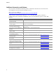
Preface Additional Information and Software If you need more information about this product or information about the accessories that can be used with this server board, use the following resources. These sources are available at http://support.intel.com/support/motherboards/server/chassis/SR1450/ Unless otherwise indicated in the table below, once on this Web page, type the document or software name in the search field at the left side of the screen and select the option to search “This Product.
Preface Safety Information WARNING Before working with your server product, whether you are using this guide or any other resource as a reference, pay close attention to the safety instructions. You must adhere to the assembly instructions in this guide to ensure and maintain compliance with existing product certifications and approvals. Use only the described, regulated components specified in this guide.
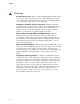
Preface Warnings System power on/off: The power button DOES NOT turn off the system AC power. To remove power from system, you must unplug the AC power cord from the wall outlet. Make sure the AC power cord is unplugged before you open the chassis, add, or remove any components. Hazardous conditions, devices and cables: Hazardous electrical conditions may be present on power, telephone, and communication cables.
Preface Safety Cautions Read all caution and safety statements in this document before performing any of the instructions. See also Intel Server Boards and Server Chassis Safety Information or at http://support.intel.com/support/motherboards/server/sb/CS-010770.htm Wichtige Sicherheitshinweise Lesen Sie zunächst sämtliche Warn- und Sicherheitshinweise in diesem Dokument, bevor Sie eine der Anweisungen ausführen.
Contents Warnings .......................................................................................................viii 1 Server Chassis Features ............................................................................. 14 Component Identification ...................................................................................................... 17 Internal Components ....................................................................................................
Contents Installing a PCI Add-in Card ......................................................................................... 47 Removing a PCI Add-in Card ....................................................................................... 49 Replacing the Standard Control Panel.................................................................................. 50 ® Replacing the Intel Local Control Panel...............................................................................
Contents Extent of Limited Warranty.................................................................................................... 85 Warranty Limitations and Exclusions .................................................................................... 86 Limitations of Liability ................................................................................................... 86 How to Obtain Warranty Service..........................................................................................
Contents Figure 41. Figure 42. Figure 43. Figure 44. Figure 45. Figure 46. Figure 47. Figure 48. Figure 49. Figure 50. Removing the Power Supply Air Duct....................................................................... 56 Removing a Power Supply Fan Module ................................................................... 57 Removing the Power Distribution Board ................................................................... 59 Installing the Power Distribution Board ...........................
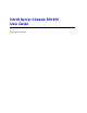
1 Server Chassis Features This chapter briefly describes the main features of Intel® Server Chassis SR1450. This chapter provides drawings of the product, a list of the server features, and diagrams showing the location of important components and connections on the server chassis. The Intel Server Chassis SR1450 is shown in the following drawing. TP01584 Figure 1.
Server Chassis Features Table 1 summarizes the major features of the server chassis. 4 Table 1.
Server Chassis Features Table 1.
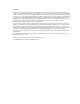
Server Chassis Features Component Identification Internal Components The diagram below shows the server chassis with a server board installed into it. D E C B A F M G H L K I J TP01585 A. Single system PCI fan B. Power supply fan modules C. Power supply air duct D. Rear power supply module E. PCI Riser assembly F. Server board G. Processor air duct. H. System fan module I. SATA or SCSI backplane J. Control panel (Standard Control Panel shown) K. Drive bay area (drives not included) L.
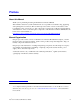
Server Chassis Features Standard Control Panel The diagram below shows the features available on the Standard Control Panel. The Standard Control Panel is one of two required front panel options that can be selected. The other option is the Intel® Local Control Panel. For instructions on installing the Standard Control Panel, see “Replacing the Standard Control Panel.” A B C D E F G H I J K TP01586 Callout A Feature USB 2.
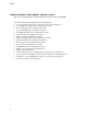
Server Chassis Features Intel® Local Control Panel ® The diagram below shows the features available on the Intel Local Control Panel. The Intel Local Control Panel is one of two required front panel options that can be selected. The other option is the Standard Control Panel. For instructions on installing the Standard Control Panel, see “Replacing the Intel® Local Control Panel”. ✏ NOTE ® This control panel requires the installation of the Intel Management Module, Professional or Advance Edition.
Server Chassis Features Callout J Feature System Status LED Function Solid green indicates normal operation. Blinking green indicates degraded performance. Solid amber indicates a critical or non-recoverable condition. Blinking amber indicates a non-critical condition. No light indicates POST is running or the system is off. K NIC 2 activity LED L NIC 1 activity LED Continuous green light indicates a link between the system and the network to which it is connected.
Server Chassis Features Peripheral Devices (Front Features) The chassis provides locations and hardware for installing hard drives, a floppy drive, CD-ROM drive, or DVD-ROM drive. The drives must be purchased separately. The following figure shows the available options. A B C D TP01589 A. B. C. D. Front power supply module Slimline floppy drive or DVD-ROM drive or CD-ROM drive Control panel (Local Control Panel shown) Hard drive bays (3) Figure 6.
Server Chassis Features Floppy / CD-ROM / DVD-ROM Slimline Carriers The slimline drive carriers can be used with one slimline floppy, CD-ROM or DVD-ROM drive. There are two carriers that ship with the chassis; one carrier is for a CD-ROM or DVD-ROM, and the other is for a slimline floppy. Unless the optional kit to convert a hard drive bay to a floppy drive bay is used, you cannot install both a CD-ROM / DVD-ROM drive and a floppy drive.
Server Chassis Features Rack-Mounted Systems ® Your Intel Server Chassis SR1450 is designed to be mounted into a rack. You must choose from one of two accessories. The Intel Server Chassis SR1450 comes ready for mounting using the Tool-less Rail Kit (AXXHERAIL). This option can also support a Cable Management Arm (APLCARM). The second option is a fixed rail kit (AXXBRACKETS). This option requires some integration to the chassis. It does not support a Cable Management Arm.
2 Hardware Installations and Upgrades Before You Begin Before working with your server product, pay close attention to the safety instructions at the beginning of this manual. See “Safety Information.” This document provides instructions for adding and replacing chassis components. For instructions on replacing components on the server board, such as the processor and memory DIMMs, see the instructions provided with the server board.
Hardware Installations and Upgrades Removing and Installing the Chassis Cover Removing the Chassis Cover The Server Chassis SR1450 must be operated with the top cover in place to ensure proper cooling. You will need to remove the top cover to add or replace components inside of the platform. Before removing the top cover, power down the server and unplug all peripheral devices and the AC power cable(s). None of the components accessible through the top cover are hot-swappable.
Hardware Installations and Upgrades Installing the Chassis Cover 1. Place the cover over the chassis so that the side edges of the cover sit just inside the chassis sidewalls. 2. Slide the cover forward until it clicks into place. See letter “A” in the figure below. 3. (Optional) Insert the shipping screw at the center of the top cover. 4. Reconnect all peripheral devices and the AC power cord. A TP01591 Figure 8.
Hardware Installations and Upgrades Removing and Installing the Front Bezel The front bezels are available as optional accessories for the Server Chassis SR1450. Two front bezel options are available. One is used for the Standard Control Panel and the other is used with ® the Intel Local Control Panel. See the diagrams below to identify your front bezel. Note the orientation in the figures below – the control panel is at the right.
Hardware Installations and Upgrades Installing the Front Bezel Use the steps below if your system includes either the standard front bezel or the front bezel for the Intel Local Control Panel. The front bezel is optional. 1. At each end of the bezel, line up the center notch on the bezel with the center guide on the rack handles. 2. Push the bezel onto the front of the chassis until it clicks into place. 3. Lock the bezel. 4.
Hardware Installations and Upgrades Removing the Processor Air Duct 1. Observe the safety and ESD precautions at the beginning of this book. See “Safety Information.” 2. Power down the server and unplug all peripheral devices and the AC power cable(s). 3. Remove the chassis cover. For instructions, see “Removing the Chassis Cover.” 4. Lift the processor air duct from its location over the two processor sockets. n Fa 4B / 4A n Fa 3B / 3A n Fa 2B / 2A n Fa 1B / 1A TP01596 Figure 13.
Hardware Installations and Upgrades TP01597 Figure 14. Preparing the Processor Air Duct 5. Place the processor air duct over the processor socket(s). See the figure below. The front edge of the air duct should contact the fan module and the top of the installed air duct should be flush with the top surface of the fan module. Use caution not to pinch or disengage cables that may be near or under the air duct. n Fa 4B / 4A n Fa 3B / 3A n Fa 2B / 2A n Fa 1B / 1A TP01598 Figure 15.
Hardware Installations and Upgrades Installing and Removing a Hard Disk Drive Up to three hard drives of one of the following types can be installed, depending on the hard drive installation option used in your server chassis and the drives supported by your server board. Three hot-swap SCSI drives if the SCSI backplane is installed. Three hot-swap SATA drives if the SATA backplane is installed. ✏ NOTE The Intel Server Chassis SR1450 does not support all hard drives.
Hardware Installations and Upgrades 4. Remove the four screws that attach the plastic baffle or the previously installed hard drive to the drive carrier. Two screws are at each side of the baffle or the hard drive. If required, store the plastic baffle for future use. B A TP01600 Figure 17. Removing the Baffle from a Hot-swap Drive Carrier Installing a SATA or SCSI Hot-swap Hard Disk Drive 1. Remove the hard drive from its wrapper and place it on an antistatic surface. 2.
Hardware Installations and Upgrades 6. When the black drive carrier lever begins to close by itself, push on it to lock the drive assembly into place. A B TP01602 Figure 19. Inserting a Hot-swap Hard Disk Drive Assembly into the Chassis 7. (Optional) Install the front bezel. For instructions, see “Removing and Installing the Front Bezel.
Hardware Installations and Upgrades Installing a Floppy Drive into Slimline Bay Use these instructions if you are installing a floppy drive into the slimline drive bay at the upper left side of your chassis. ✏ NOTE The carrier for the slimline floppy drive that is used in these instructions was sent to you in the hardware kit that came with your Server Chassis SR1450. 1. Observe the safety and ESD precautions at the beginning of this book. See “Safety Information.” 2.
Hardware Installations and Upgrades 7. Open the connector on the rear of the floppy drive by pulling up on the connector cover. See letter “A” in the figure below. 8. Insert one end of the 26-pin floppy drive flat flex cable end into the connector. See letter “B” in the figure below. 9. Push down on the connector cover to lock the cable into place. See letter “C” in the figure below. C B A TP01604 Figure 21. Installing Floppy Flat Flex Cable to a Floppy Drive 10.
Hardware Installations and Upgrades 13. Connect the floppy drive data cable that was included with your kit between the interposer board and the server board. See letters “B” and “C” in the figure. See your server board documentation for assistance in locating the connector location on the server board. 14. Connect the longest of the two device power cables coming from the backplane power connector. See letter “D” in the figure. B A C D TP01606 Figure 23.
Hardware Installations and Upgrades 14. Install the chassis cover. For instructions, see “Installing the Chassis Cover.” 15. (Optional) Install the front bezel. For instructions, see “Removing and Installing the Front Bezel.” 16. Plug all peripheral devices and the AC power cable(s) back into the server. Installing a Floppy Drive into the Converted Hard Drive Bay The slimline floppy drive conversion kit must be installed in the center hard drive bay. 1.
Hardware Installations and Upgrades 7. Slide the floppy drive into the drive carrier, rear of the drive first, with the underside of the drive facing down. 8. Line up the holes in the side of the drive with the holes in the carrier. See letter “A” in the figure below. A A TP01610 Figure 25. Inserting a Drive into the Floppy Conversion Kit Carrier 9. Attach the floppy drive to the carrier with the screws that came with your floppy drive conversion kit. One screw attaches at each side.
Hardware Installations and Upgrades 10. Reattach the slide rails onto floppy drive conversion kit carrier. See the figure below. TP01309 Figure 27. Install the Rails onto the Floppy Drive Conversion Kit Carrier 11. Open the connector on the rear of the floppy drive by pulling up on the connector cover. See letter “A” in the figure below. 12. Insert one end of the flat flex cable end into the floppy drive connector. See letter “B” in the figure. 13.
Hardware Installations and Upgrades 14. Attach the other end of the flat flex cable to the interposer board. 15. Install the interposer board into the floppy drive conversion kit carrier. One screw attaches on the right side. 16. Slide the carrier assembly into center hard drive bay until it clicks into place. 17. Attach the power and data cables to the interposer board. 18. Attach the other end of the power and data cables to the server board. 19. Install the chassis cover.
Hardware Installations and Upgrades Installing or Removing a CD-ROM or DVD-ROM Drive CAUTION CD-ROM and DVD-ROM drives are NOT hot swappable. Before removing or replacing the drive, you must first take the server out of service, turn off all peripheral devices connected to the system, turn off the system by pressing the power button, and unplug the AC power cord from the system or wall outlet.
Hardware Installations and Upgrades 9. Slide the DVD-ROM / CD-ROM drive carrier into the chassis. See letter “A” in the figure below. 10. Attach the 44-pin CD-ROM drive cable to the exposed side / back of the interposer board. See letter “B” in the figure below. 11. Connect the loose end of the CD-ROM drive cable to the server board IDE connector. See letter “C” in the figure below. 12. Connect the longest of the two device power cables coming from the backplane power connector.
Hardware Installations and Upgrades Removing a CD-ROM or DVD-ROM Drive from the Slimline Bay 1. Observe the safety and ESD precautions at the beginning of this book. See “Safety Information.” 2. Power down the server and unplug all peripheral devices and the AC power cable(s). 3. Remove the chassis cover. For instructions, see “Removing the Chassis Cover.” 4. Remove the front bezel if it is installed. For instructions, see “Removing and Installing the Front Bezel.” 5.
Hardware Installations and Upgrades Installing a PCI Riser Card To install the PCI riser card, use the following instructions. 1. Observe the safety and ESD precautions at the beginning of this book. See “Safety Information.” 2. Power down the server and unplug all peripheral devices and the AC power cable(s). 3. Remove the chassis cover. For instructions, see “Removing the Chassis Cover.” 4. Pull up on the two latches on the assembly. 5. Lift the PCI riser assembly from the chassis. TP01615 Figure 31.
Hardware Installations and Upgrades 6. 7. 8. 9. 10. Line up the stand-offs on the riser assembly with the slot and the large hole on the riser card. Press and hold the blue riser locking lever. See letter “A” in the figure below. Place riser card onto the stand-offs. See letter “B” in the figure below. Slide the riser card to the right to lock it into place. Release the blue locking lever. Figure 32. Installing an Add-in Card into the PCI Riser Assembly 11. Install a PCI add-in card, if desired.
Hardware Installations and Upgrades Removing a PCI Riser Card The PCI riser card can be replaced if it fails or if a different option is required. To replace the PCI riser card, use the following instructions to remove it, and then follow the instructions under “Installing a PCI Riser Card” to install a new riser card. ✏ NOTE To eliminate the possibility of installing the replacement card on the wrong side of the PCI riser assembly, replace one card at a time. 1.
Hardware Installations and Upgrades Installing and Removing a PCI Add-in Card Installing a PCI Add-in Card In the slot provided by the PCI riser card, you can install one add-in card. Use the following instructions to install an add-in card. 1. Observe the safety and ESD precautions at the beginning of this book. See “Safety Information.” 2. Power down the server and unplug all peripheral devices and the AC power cable(s). 3. Remove the chassis cover. For instructions, see “Removing the Chassis Cover.” 4.
Hardware Installations and Upgrades 6. 7. 8. 9. 10. Open the PCI retention clip on the PCI riser card assembly. See letter “A” in the figure below. Remove the filler panel at the back of the riser assembly. See letter “B” in the figure below. Insert the add-in card until it seats in riser card connector. See letter “C”. Make sure the add-in card bracket inserts into slot. See letter “D”. Close the retention clip. See letter “A” in the figure. A B D C TP01617 Figure 35.
Hardware Installations and Upgrades Removing a PCI Add-in Card 1. Observe the safety and ESD precautions at the beginning of this book. See “Safety Information.” 2. Power down the server and unplug all peripheral devices and the AC power cable(s). 3. Remove the chassis cover. For instructions, see “Removing the Chassis Cover.” 4. Pull up on the two latches on the riser assembly. 5. Lift the PCI riser assembly from the chassis. 6. Open the PCI retention clip on the PCI riser card assembly. 7.
Hardware Installations and Upgrades Replacing the Standard Control Panel Your server must be operated with a control panel installed. The steps for replacing the Standard Control Panel are listed below. CAUTION The control panel is NOT hot swappable.
Hardware Installations and Upgrades Replacing the Intel® Local Control Panel Your server must be operated with a control panel installed. The steps for replacing the Intel Local Control Panel are listed below. CAUTION The control panel is NOT hot swappable.
Hardware Installations and Upgrades 8. If using a bezel with the Local Control Panel, change out the LCP plastic front panel on the replacement control panel. If you are not using the optional bezel, make sure the back half of the tray is secured in the “shortened” position. 9. Connect the front panel cable and the USB cable to the replacement control panel. 10. Slide the replacement LCP/tray assembly into the chassis until the release lever clicks into place. 11. Install the chassis cover.
Hardware Installations and Upgrades Replacing System Fan(s) The system fans at the front of the Server Chassis SR1450 can be individually replaced if one of them fails. Use the steps below to replace a dual rotor fan. CAUTION The system fans are NOT hot swappable.
Hardware Installations and Upgrades 8. Note the position of the raised arrows in the top of the replacement fan. Position the fan so one arrow points to the left, and the other arrow points to the rear of the chassis. The fan cable should be pointing to the rear of the chassis. 9. With the fan arrows oriented correctly, insert the replacement fan into the fan module. 10. Connect the power cable for the fan into the fan distribution board. 11. Install the processor air duct.
Hardware Installations and Upgrades B A TP01626 Figure 40. Removing the Single System PCI Fan 6. Note the position of the raised arrows in the top of the replacement fan. Position the fan so one arrow points to the left, and the other arrow points to the rear of the chassis. The fan cable should be pointing to the rear of the chassis. 7. With the fan arrows oriented correctly, insert the replacement fan into the fan housing. 8. Connect the fan into the fan connector. 9. Install the chassis cover.
Hardware Installations and Upgrades Removing the Power Supply Air Duct Use the steps below to remove the power supply air duct. 1. Observe the safety and ESD precautions at the beginning of this book. See “Safety Information.” 2. Power down the server and unplug all peripheral devices and the AC power cable(s). 3. Remove the chassis cover. For instructions, see “Removing the Chassis Cover.” 4. Remove cables from the air duct channel. 5. Remove the screw from the power supply air duct.
Hardware Installations and Upgrades Replacing a Power Supply Fan Module The power supply fan modules in the Server Chassis SR1450 can be individually replaced if one of them fails. Use the steps below to replace a dual rotor fan. CAUTION The power supply fan module is NOT hot swappable.
Hardware Installations and Upgrades Replacing the Power Distribution Board The power distribution board is located between the two power supplies. This board can be replaced if it fails. To replace the power distribution board, use the following instructions. 1. Observe the safety and ESD precautions at the beginning of this book. See “Safety Information.” 2. Power down the server and unplug all peripheral devices and the AC power cable(s). 3. Remove the chassis cover.
Hardware Installations and Upgrades L K C E P Q A K B D F H G I G J TP01629 Figure 43. Removing the Power Distribution Board 15. Line up the holes on the replacement power distribution board with the power supply stand-offs on chassis. See letter “A” in “Figure 44. Installing the Power Distribution Board”. Press down and slide the power distribution board to the left until it sits firmly in place. See letter “B” in “Figure 44”. 16.
Hardware Installations and Upgrades 23. If a slimline DVD/CD-ROM or floppy drive is installed, connect power (see letter “J” in “Figure 44”) and data cable (see letter “K” in “Figure 44”). 24. Connect the PCI fan. See letter “L” in “Figure 44”. 25. Install the chassis cover. For instructions, see “Installing the Chassis Cover.” 26. Plug all peripheral devices and the AC power cable(s) back into the server. A B E F C B D L G I H J H K TP01628 Figure 44.
Hardware Installations and Upgrades Replacing the Hot-Swap Power Supply The power supply can be replaced if it fails. If your server uses a redundant power supply, you do not need to power down your server to replace the failed power supply, as long as the remaining power supply is plugged into an AC power source and is functioning. If you do not have a redundant power supply installed, you must power down your server system before replacing the power supply.
Hardware Installations and Upgrades A B TP01630 Figure 46. Removing the Rear Hot-Swap Power Supply from the Chassis Installing a Hot-Swap Power Supply To install a replacement power supply or to add a redundant power supply, use the following instructions. 1. (Replacing power supply only) Remove the failed power supply. For instructions see “Removing a Hot-Swap Power Supply”. 2. (Installing redundant power supply only): Remove the filler panel from the rear power supply bay by pulling it out. 3.
Hardware Installations and Upgrades Removing and Installing the SATA or SCSI Backplane Your server chassis must be configured with one of the following drive installation options: A hot-swap SCSI option that came with a SCSI backplane board. A hot-swap SATA option that came with a SATA backplane board. CAUTION The backplane is tool-less, but NOT hot swappable.
Hardware Installations and Upgrades Removing the SATA or SCSI Backplane 1. Observe the safety and ESD precautions at the beginning of this book. See “Safety Information.” 2. Power down the server and unplug all peripheral devices and the AC power cable(s). 3. Remove the chassis cover. For instructions, see “Removing the Chassis Cover.” 4. Remove all hot-swap drive carriers. For instructions, see “Removing a SATA or SCSI Hotswap Hard Disk Drive.” 5. Disconnect all cables from the backplane: 6.
Hardware Installations and Upgrades Installing the SATA or SCSI Backplane 1. Observe the safety and ESD precautions at the beginning of this book. See “Safety Information.” 2. Power down the server and unplug all peripheral devices and the AC power cable(s). 3. Remove the chassis cover. For instructions, see “Removing the Chassis Cover.” 4. Remove all hot-swap drive carriers. For instructions, see “Removing a SATA or SCSI Hotswap Hard Disk Drive.” 5.
Hardware Installations and Upgrades 8. Connect the following cables to the backplane: Front panel cable Power cable (SCSI backplane only): SCSI Channel A cable. The cable indicates the end that is to be connected to the backplane. (SATA backplane only): SATA cable(s). 9. Install the chassis cover. For instructions, see “Installing the Chassis Cover.” 10. Install the hot-swap hard drive(s), if applicable. For instructions, see “Installing a SATA or SCSI Hot-swap Hard Disk Drive”. 11.
Technical Reference Cable Routing When you add or remove components from your server chassis, make sure your cables are routed correctly before reinstalling the chassis cover. Use caution to make sure no cables or wires are pinched and that the airflow from the fans is not blocked. Use the tables and figure below to determine the correct cable routing. A B C D TP01611 Figure 49. SCSI Cable Routing Through Notches in Metal Air Baffle Table 2.
Technical Reference A B E C D TP01612 Figure 50. SATA Cable Routing Through Notches in Metal Air Baffle Table 3.
Technical Reference Power Supply Specifications 520-W Single Power Supply Input Voltages 100-127 V∼ at 50/60 Hz; 6.7 A max. 200-240 V∼ at 50/60 Hz; 3.4 A max. 520-W Single Power Supply Output Voltages The table below lists the total wattage available from the power subsystem for each voltage. Ensure that your loads do not exceed the combined total wattage of 520 Watts. For information about calculating the power usage for your configuration, see “Calculating Power Usage.” Table 4.
Technical Reference System Environmental Specifications Table 5. Environmental Specifications Temperature Non-operating Operating Humidity Non-operating –40 ° to 70 °C. +10°C to +35°C with the maximum rate of change not to exceed 10°C per hour 90% relative humidity (non-condensing) at 35 °C. Shock Operating Packaged 70 2.0 g, 11 msec, 1/2 sine Non-palletized free fall in height 24 inches. Acoustic noise Sound Pressure: 55 dBA (Rackmount) in an idle state at typical office ambient temperature.
Equipment Log and Worksheets Equipment Log Use this equipment log to record information about your server.
Equipment Log and Worksheets Current Usage Calculating Power Usage The total combined wattage for your configuration must be less than the wattage rating for your power supply. Use the worksheets in this section to calculate the total used by your configuration. See the documentation that came with your add-in boards for their current and voltage information. Worksheet, Calculating DC Power Usage Table 6. Power Usage Worksheet 1 Current (maximum) at voltage level: Device +3.
Equipment Log and Worksheets Worksheet, Total Combined Power Used by the Server 1. From the previous worksheet, enter the total current for each column. 2. Multiply the voltage by the total current to get the total wattage for each voltage level. 3. Add the total wattage for each voltage level to arrive at the total combined power usage for the power subsystem. Table 7. Power Usage Worksheet 2 Voltage level and total current (V X A = W) Total Watts for each voltage level (+3.
Regulatory and Compliance Information Product Regulatory Compliance Product Safety Compliance The Server Chassis SR1450 complies with the following safety requirements: UL60950 – CSA 60950(USA / Canada) EN60950 (Europe) IEC60950 (International) CB Certificate & Report, IEC60950 (report to include all country national deviations) GS License (Germany) GOST R 50377-92 - License (Russia) Belarus License (Belarus) Ukraine License (Ukraine) CE - Low Voltage Directive 73/23/EEE (Europe) IRAM Ce
Regulatory and Compliance Information Certifications / Registrations / Declarations UL Certification (US/Canada) CE Declaration of Conformity (CENELEC Europe) FCC/ICES-003 Class A Attestation (USA/Canada) VCCI Certification (Japan) C-Tick Declaration of Conformity (Australia) MED Declaration of Conformity (New Zealand) BSMI Certification (Taiwan) GOST R Certification / License (Russia) Belarus Certification / License (Belarus) RRL Certification (Korea) IRAM Certification (Argenti
Regulatory and Compliance Information Table 8. Product Certification Markings (continued) Regulatory Compliance Country BSMI Certification Number & Class A Warning Taiwan GOST R Marking Russia RRL MIC Mark Korea China Compulsory Certification Mark China Marking Electromagnetic Compatibility Notices FCC (USA) This device complies with Part 15 of the FCC Rules.
Regulatory and Compliance Information This equipment has been tested and found to comply with the limits for a Class A digital device, pursuant to Part 15 of the FCC Rules. These limits are designed to provide reasonable protection against harmful interference in a residential installation. This equipment generates, uses, and can radiate radio frequency energy and, if not installed and used in accordance with the instructions, may cause harmful interference to radio communications.
Regulatory and Compliance Information VCCI (Japan) English translation of the notice above: This is a Class A product based on the standard of the Voluntary Control Council for Interference (VCCI) from Information Technology Equipment. If this is used near a radio or television receiver in a domestic environment, it may cause radio interference. Install and use the equipment according to the instruction manual.
Regulatory and Compliance Information Regulated Specified Components To maintain the UL listing and compliance to other regulatory certifications and/or declarations, the following regulated components must be used and conditions adhered to. Interchanging or use of other component will void the UL listing and other product certifications and approvals. Updated product information for configurations can be found on the Intel Server Builder Web site at the following URL: http://channel.intel.
Getting Help World Wide Web http://support.intel.com/support/motherboards/server/SR1450 Telephone All calls are billed US $25.00 per incident, levied in local currency at the applicable credit card exchange rate plus applicable taxes. (Intel reserves the right to change the pricing for telephone support at any time without notice). Before calling, fill out the “Issue Report Form” on the following pages. In U.S.
Intel Server Issue Report Form ® Intel Server Issue Report Form Date Submitted: Company Name: Contact Name: Email Address: Intel Server Product: Priority (Critical, Hot, High, Low): Brief Problem Description. Provide a brief description below. See the last page for space to include a detailed problem description.
Operating System Information Operating System Version Service Pack # Peripheral Information Check each box below that is used, and provide the requested information Peripheral Card Or Peripheral Description Add-in Cards Add-in Card Add-in Card Add-in Card Video On-Board Video Add-in Video NIC On-Board NIC1 On-Board NIC2 Hard Drive Information: IDE # of drives installed: Make/Model/Firmware Revision SCSI # of drives installed: Make/Model/Firmware Revision SATAI # of
Intel Server Issue Report Form Complete Problem Description In the space below, provide a complete description of the steps used to reproduce the problem or a complete description of where the problem can be found. Please also include any details on troubleshooting already done.
Warranty Limited Warranty for Intel® Chassis Subassembly Products Intel warrants that the Products (defined herein as the Intel® chassis subassembly and all of its various components and software delivered with or as part of the Products) to be delivered hereunder, if properly used and installed, will be free from defects in material and workmanship and will substantially conform to Intel’s publicly available specifications for a period of three (3) years after the date the Product was purchased from an Int
Warranty Warranty Limitations and Exclusions These warranties replace all other warranties, expressed or implied including, but not limited to, the implied warranties of merchantability and fitness for a particular purpose. Intel makes no expressed warranties beyond those stated here. Intel disclaims all other warranties, expressed or implied including, without limitation, implied warranties of merchantability and fitness for a particular purpose.
Warranty How to Obtain Warranty Service To obtain warranty service for this Product, you may contact Intel or your authorized distributor. North America and Latin AmericaTo obtain warranty repair for the product, please go to the following Web site to obtain instructions: http://support.intel.com/support/motherboards/draform.htm In Europe and in AsiaContact your original authorized distributor for warranty service.