
Datasheet

Functional Architecture Intel® Server System SR1640TH TPS
Revision 1.0
Intel order number: E94847-001
54
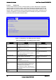
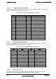
2.7.1.3 Front Control Panel Connector
The server board S3420TH provides a 34-pin front panel connector (J8K1). The following
table provides the pin-out for this connector.
Table 40. Front Control Panel header pin-out (J8K1)
Pin # Signal Pin # Signal
1 P3V3_AUX 2 P5V_STBY_SYS
3 KEY 4 P3V3_AUX_node2
5 P3V3 6 P3V3_node2
7 FP_ID_N_LED_node1 8 FP_ID_N_LED_node2
9 LED_Status_Green_N 10 LED_Status_Green_N_node2
11 LED_Status_Amber_N 12 LED_Status_Amber_N_node2
13 LED_NIC1_ACT_BUF_N 14 LED_NIC1_ACT_BUF_N_node2
15 NC 16 NC
17 SMB_SENS_3V3SB_DAT 18 SMB_SENS_3V3SB_DAT_node2
19 SMB_SENS_3V3SB_CLK 20 SMB_SENS_3V3SB_CLK_node2
21 LED_NIC2_ACT_BUF_N 22 LED_NIC2_ACT_BUF_N_node2
23 NC 24 NC
25 FP_PWR_LED_N 26 FP_PWR_LED_N_node2
27 FP_PWR_BTN_N 28 FP_PWR_BTN_N_node2
29 RST_FP_BTN_N 30 RST_FP_BTN_N_node2
31 FP_ID_BTN_N 32 FP_ID_BTN_N_node2
33 GND 34 GND
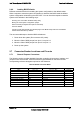
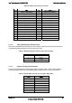
2.7.1.4 Front Panel USB Connector
The server board S3420TH provides a 24-pin front panel USB connector (J7K1). The
following table provides the pin-out for this connector.
Table 41. Front Panel USB header pin-out (J7K1)
Pin # Signal Pin # Signal
1 P5V 2 P5V_node2
3 P5V_USB_PWR24 4 P5V_USB_PWR24_node2
5 P5V_USB_PWR24 6 P5V_USB_PWR24_node2
7 USB_PCH_2_FB_DN 8 USB_PCH_2_FB_DN_node2
9 USB_PCH_2_FB_DP 10 USB_PCH_2_FB_DP_node2
11 GND 12 GND
13 USB_PCH_4_FB_DN 14 USB_PCH_4_FB_DN_node2
15 USB_PCH_4_FB_DP 16 USB_PCH_4_FB_DP_node2
17 GND 18 GND
19 USB_PCH_8_FB_DN 20 USB_PCH_8_FB_DN_node2
21 USB_PCH_8_FB_DP 22 USB_PCH_8_FB_DP
23 GND 24 GND
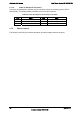
2.7.1.5 SAS 4i Connector
The server board S3420TH provides a 32-pin SATA/SAS connector (J9J2) for HDD
connection. The following table provides the pin-out for this connector.