G4H875-N G4H875-C G4H875-B Rev.
Copyright This publication contains information that is protected by copyright. No part of it may be reproduced in any form or by any means or used to make any transformation/adaptation without the prior written permission from the copyright holders. This publication is provided for informational purposes only.
Battery: • Danger of explosion if battery incorrectly replaced. • Replace only with the same or equivalent type recommend by the manufacturer. • Dispose of used batteries according to the batter y manufacturer’s instructions. Joystick or MIDI port: • Do not use any joystick or MIDI device that requires more than 10A current at 5V DC. There is a risk of fire for devices that exceed this limit.
Notice An electronic file of this manual is included in the CD. To view the user’s manual, insert the CD into a CD-ROM drive. The autorun screen (Main Board Utility CD) will appear. Click “User’s Manual” on the main menu.
Table of Contents Chapter 1 - Introduction 1.1 Features and Specifications.................................................................................. 7 1.2 Hyper-Threading Technology Functionality Requirements..... 15 1.3 Package Checklist............................................................................................................. 15 Chapter 2 - Hardware Installation 2.1 2.2 2.3 2.4 2.5 2.6 System Board Layout .........................................................................
1 Introduction Appendix A - Enabling the Hyper-Threading Technology A.1 Enabling the Hyper-Threading Technology......................................... 114 Appendix B - CPU Fan Protection B.1 CPU Fan Protection............................................................................................. 117 Appendix C - CPU Temperature Protection C.1 CPU Temperature Protection....................................................................... 118 Appendix D - System Error Messages D.1 POST Beep....
Introduction 1 Chapter 1 - Introduction 1.1 Features and Specifications 1.1.1 Features Chipset • Intel® 875P chipset - Intel® 82875P Memory Controller Hub (MCH) - Intel® Hance Rapids I/O Controller Hub Processor The system board is equipped with Socket 478 for installing one of the following supported processors. • Intel® Pentium® 4 (Prescott and Northwood) processor up to 3.
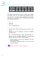
1 Introduction Density 128 Mbit 256 Mbit 512 Mbit Density Width X8 X16 X8 X16 X8 X16 Single/Double SS/DS SS/DS SS/DS SS/DS SS/DS SS/DS 184-pin DDR 128/256MB 64MB/NA 256/512MB 128MB/NA 512/1024MB 256MB/NA Performance Acceleration Technology (PAT) PAT mode is supported only when the system uses DDR400 with 800MHz FSB CPU. PAT performs data transactions directly from the CPU to the system memory, bypassing the normal path of operation.
Introduction 1 Onboard Audio Features • 18-bit stereo full-duplex codec with independent variable sampling rate • High quality differential CD input • True stereo line level outputs • 2-channel audio output Onboard LAN Features • 82547EI Gigabit LAN CSA interface (G4H875-N only) - Integrated power management functions - Full duplex support at both 10, 100 and 1000 Mbps - Supports IEEE 802.
1 Introduction USB Ports The system board supports USB 2.0 and USB 1.1 ports. USB 1.1 suppor ts 12Mb/second bandwidth while USB 2.0 suppor ts 480Mb/second bandwidth providing a marked improvement in device transfer speeds between your computer and a wide range of simultaneously accessible external Plug and Play peripherals. BIOS • Award BIOS, Windows ® 98SE/2000/ME/XP Plug and Play compatible • Supports DMI 2.
Introduction 1 I/O Connectors • 1 connector for 2 additional external USB 2.0/1.
1 Introduction 1.1.3 Intelligence CPU Fan Protection The CPU Fan Protection function has the capability of monitoring the CPU fan when the system boots. Once it has detected that the CPU fan did not rotate, 5 warning beeps will sound then the system will automatically power-off. This preventive measure has been added to protect the CPU from damage and insure a safe computing environment.
Introduction 1 Wake-On-LAN This feature allows the network to remotely wake up a Soft Power Down (Soft-Off) PC. It is supported via the onboard LAN port, via a PCI LAN card that uses the PCI PME (Power Management Event) signal or via a LAN card that uses the Wake-On-LAN connector. However, if your system is in the Suspend mode, you can power-on the system only through an IRQ or DMA interrupt. Important: The 5VSB power source of your power supply must support ≥720mA.
1 Introduction ACPI The system board is designed to meet the ACPI (Advanced Configuration and Power Interface) specification. ACPI has energy saving features that enables PCs to implement Power Management and Plug-and-Play with operating systems that support OS Direct Power Management. Currently, only Windows® 98SE/2000/ME/XP supports the ACPI function. ACPI when enabled in the Power Management Setup will allow you to use the Suspend to RAM function.
Introduction 1 1.2 Hyper-Threading Technology Functionality Requirements Enabling the functionality of Hyper-Threading Technology for your computer system requires ALL of the following platforms.
2 Hardware Installation Chapter 2 - Hardware Installation 2.
Hardware Installation KB/Mouse COM 1 1 CPU fan PS/2 KB/Mouse power select (JP2) 1 2 1 1 2nd fan +12V power ATX power USB 1-4 power select (JP3) COM 2 DIMM Standby LED Socket 478 Parallel 1 1 Power-on select (JP6) IDE 2 IDE 1 1 1 USB 3-4 North bridge fan LAN; USB 1-2 Intel Line-out Line-in Mic-in 82875P Channel 0 82551QM 1 DDR 2 DDR 1 DDR 1 AGP Intel DDR 2 1 Channel 1 PCI Slot 1 Clear CMOS (JP5) 1 Chassis open (J6) 1 SATA 2 PCI Standby LED PCI Slot 2 BIOS Write Prote
2 Hardware Installation KB/Mouse COM 1 1 CPU fan PS/2 KB/Mouse power select (JP2) 1 1 1 2nd fan +12V power ATX power USB 1-2 power select (JP3) COM 2 DIMM Standby LED Socket 478 Parallel 1 1 Power-on select (JP6) IDE 2 IDE 1 1 1 North bridge fan LAN 1; USB 1-2 Intel Line-out Line-in Mic-in 82875P Channel 0 82551QM 1 DDR 2 DDR 1 DDR 1 AGP Intel DDR 2 1 Channel 1 PCI Slot 1 Clear CMOS (JP5) 1 Chassis open (J6) 1 SATA 2 PCI Standby LED PCI Slot 2 1 I/O PCI Slot 3 SATA
Hardware Installation . . . . . . . . 2 Warning: Electrostatic discharge (ESD) can damage your system board, processor, disk drives, add-in boards, and other components. Perform the upgrade instruction procedures described at an ESD workstation only. If such a station is not available, you can provide some ESD protection by wearing an antistatic wrist strap and attaching it to a metal part of the system chassis.
2 Hardware Installation The system board supports the following memory interface. Single Channel (SC) Data will be accessed in chunks of 64 bits (8B) from the memory channels. Virtual Single Channel (VSC) If both channels are populated with different memory configurations, the MCH defaults to Virtual Single Channel. Dual Channel (DC) Dual channel provides better system performance because it doubles the data transfer rate.
Hardware Installation 2 BIOS Setting Configure the system memory in the Advanced Chipset Features submenu of the BIOS. The table below lists the various optimal operating modes that should be configured for the memory channel operation.
2 Hardware Installation DDR 1 DDR 2 DDR 3 DDR 4 Dynamic Mode Addressing E P(*)(2,4) DS E P(*)(2,4) DS Dynamic Mode Addressing P(*)(1,3) DS E P(*)(1,3) DS E Dynamic Mode Addressing P(*)(1,3) DS P(*)(2,4) DS P(*)(1,3) DS P(*)(2,4) DS Dynamic Mode Addressing E P(*)(2,4) SS E P(*)(2,4) SS Dynamic Mode Addressing P(*)(1,3) SS E P(*)(1,3) SS E Dynamic Mode Addressing P(*)(1,3) SS P(*)(2,4) SS P(*)(1,3) SS P(*)(2,4) SS Config P - denotes populated E - denotes empty * - denotes D
Hardware Installation 2 2.2.1 Installing the DIM Module A DIM module simply snaps into a DIMM socket on the system board. Pin 1 of the DIM module must correspond with Pin 1 of the socket. Notch Key Tab Tab Pin 1 1. Pull the “tabs” which are at the ends of the socket to the side. 2. Position the DIMM above the socket with the “notch” in the module aligned with the “key” on the socket. 3. Seat the module vertically into the socket. Make sure it is completely seated. The tabs will hold the DIMM in place.
2 Hardware Installation 2.3 CPU 2.3.1 Overview The system board is equipped with a surface mount 478-pin CPU socket. This socket is exclusively designed for installing an Intel processor. 2.3.2 Installing the CPU 1. Locate Socket 478 on the system board. 2. Unlock the socket by pushing the lever sideways, away from the socket, then lifting it up to a 90o angle. Make sure the socket is lifted to at least this angle otherwise the CPU will not fit in properly.
Hardware Installation 2 3. Position the CPU above the socket then align the gold mark on the corner of the CPU (designated as pin 1) with pin 1 of the socket. Important: Handle the CPU by its edges and avoid touching the pins. Gold mark Pin 1 4. Insert the CPU into the socket until it is seated in place. The CPU will fit in only one orientation and can easily be inserted without exerting any force. Important: Do not force the CPU into the socket.
2 Hardware Installation 5. Once the CPU is in place, push down the lever to lock the socket. The lever should click on the side tab to indicate that the CPU is completely secured in the socket. 2.3.3 Installing the Fan and Heat Sink The CPU must be kept cool by using a CPU fan with heatsink. Without sufficient air circulation across the CPU and heat sink, the CPU will overheat damaging both the CPU and system board. Note: • Only use Intel® certified fan and heat sink.
Hardware Installation 2 1. The system board comes with the retention module base already installed. Retention hole Retention hole Retention hole Retention hole Retention module base 2. Position the fan / heat sink and retention mechanism assembly on the CPU, then align and snap the retention legs’ hooks to the retention holes at the 4 corners of the retention module base.
2 Hardware Installation 3. The retention levers at this time remains unlocked as shown in the illustration below. Retention lever Retention lever 4. Move the retention levers to their opposite directions then push them down. This will secure the fan / heat sink and retention mechanism assembly to the retention module base. Note: You will not be able to push the lever down if the direction is incorrect. 5. Connect the CPU fan’s cable connector to the CPU fan connector on the system board.
Hardware Installation 2 2.4 Jumper Settings 2.4.1 Clearing CMOS Data JP5 ! 1 2 3 1-2 On: Normal (default) 1 2 3 2-3 On: Clear CMOS Data 1 2 ON If you encounter the following, a) CMOS data becomes corrupted. b) You forgot the supervisor or user password. c) You are unable to boot-up the computer system because the processor’s ratio/clock was incorrectly set in the BIOS. you can reconfigure the system with the default values stored in the ROM BIOS.
2 Hardware Installation 4. After powering-on the system, press to enter the main menu of the BIOS. 5. Select the Frequency/Voltage Control submenu and press . 6. Set the “CPU Clock Ratio” or “CPU Clock” field to its default setting or an appropriate bus clock or frequency ratio. Refer to the Frequency/Voltage Control section in chapter 3 for more information. 7. Press to return to the main menu of the BIOS setup utility. Select “Save & Exit Setup” and press . 8.
Hardware Installation 2 2.4.2 PS/2 Keyboard/Mouse Wake Up JP2 ! 3 3 2 2 1 1-2 On: VCC (default) 1 2-3 On: 5VSB 1 2 ON This jumper is used to select the power of the PS/2 Keyboard/ Mouse port. Selecting 5VSB will allow you to use the Wake-OnPS/2 Keyboard/Mouse function. BIOS Setting: “Power On Function” (“Super IO Device” section) in the Integrated Peripherals submenu of the BIOS must be set accordingly. Refer to chapter 3 for more information. . . . . . . . .
2 Hardware Installation 2.4.3 USB Keyboard Wake Up USB 1-4 (JP3) 2 2 1 1 1-2 On: VCC (default) USB 3-4 (JP4) 3 3 ! ! 3 2 1 1 2 ON 1-2 On: VCC (default) 2-3 On: 5VSB 3 2 1 2-3 On: 5VSB These jumpers are used to select the power of the USB ports. Selecting 5VSB will allow you to use the Wake-On-USB Keyboard function. On the G4H875-N and G4H875-C system boards, JP3 is for setting USB 1-4 that are at the rear I/O panel.
Hardware Installation 2 2.4.4 Power-on Select JP6 ! 3 3 2 2 1 1 1-2 On: Power-on via power button (default) 2-3 On: Power-on via AC power 1 2 ON This jumper is used to select the method of powering on the system. If you want the system to power-on once AC power comes in, set JP6 pins 2 and 3 to On. If you want to use the power button, set pins 1 and 2 to On.
2 Hardware Installation 2.4.5 BIOS Write Protect 1 2 ON “White” represents the switch’s position. ON 2 On: BIOS Write Protected 1 2 ON 1 On: Write only to BIOS utility 1 2 ON ! 1 2 SW1 1-2 Off: BIOS Not Write Protected SW1 is used to configure the BIOS Write Protect function. When this function is enabled, the system will be protected from unnecessary updating or flashing of the BIOS. It secures the BIOS therefore any updates to it will not take effect.
Hardware Installation 2 2.
2 Hardware Installation 2.5.1 PS/2 Mouse and PS/2 Keyboard Ports PS/2 Mouse " PS/2 Keyboard 1 2 ON The system board is equipped with an onboard PS/2 mouse (Green) and PS/2 keyboard (Purple) ports - both at location CN1 of the system board. The PS/2 mouse port uses IRQ12. If a mouse is not connected to this port, the system will reserve IRQ12 for other expansion cards. . . . . . . . . Warning: Make sure to turn off your computer prior to connecting or disconnecting a mouse or keyboard.
Hardware Installation 2 2.5.2 Serial Ports " COM 2 1 2 2 1 ON RD DTR DSR CTS COM 1 CD TD SG RTS RI 9" COM 3 COM 4 G4H875-N only G4H875-N is equipped with 2 onboard serial ports (COM 1: CN3 and COM 2: CN4) - both in Teal/Turquoise color. It is also equipped with two 9-pin connectors (COM 3: J14 and COM 4: J16) for connecting external serial ports. G4H875-C and G4H875-B are each equipped with COM 1 (CN3) and COM 2 (CN4). COM 3 and COM 4 are not present on these boards.
2 Hardware Installation 2.5.3 Parallel Port Parallel " 1 2 ON The system board has a standard parallel port (Burgundy) at location CN7 for interfacing your PC to a parallel printer. It supports SPP, ECP and EPP. Setting Function SPP (Standard Parallel Port) Allows normal speed operation but in one direction only. ECP (Extended Capabilities Port) Allows parallel port to operate in bidirectional mode and at a speed faster than the SPP’s data transfer rate.
Hardware Installation 2 2.5.4 Universal Serial Bus Ports USB 4 USB 3 10 9 2 1 VCC -Data +Data Ground Key 1 2 ON G4H875-N/C/B " USB 3-4 (J12) USB 2 USB 1 VCC -Data +Data Ground N. C. " " G4H875-N/C only G4H875-B only The system board supports USB 2.0/1.1 ports. USB allows data exchange between your computer and a wide range of simultaneously accessible external Plug and Play peripherals. G4H875-N and G4H875-C are each equipped with four onboard USB 2.0/1.
2 Hardware Installation BIOS Setting Configure USB in the Integrated Peripherals submenu (“Onboard Device” section) of the BIOS. Refer to chapter 3 for more information. Driver Installation You may need to install the proper drivers in your operating system to use the USB device. Refer to your operating system’s manual or documentation for more information. If you are using a USB 2.0 device, install the “Intel USB 2.0 Drivers”. Refer to chapter 4 for more information.
Hardware Installation 2 2.5.5 RJ45 LAN Port LAN 2 " " G4H875-N only LAN 1 1 2 ON G4H875-N is equipped with 2 onboard RJ45 LAN ports. LAN 1 which is controlled by the Intel 82551QM chip is at location CN6 and LAN 2 which is controlled by the Intel Gigabit 82547EI chip is at location CN5. G4H875-C and G4H875-B are each equipped with the LAN 1 port only. LAN allows the system board to connect to a local area network by means of a network hub.
2 Hardware Installation 2.5.6 Audio Mic-in Line-in " 1 2 Front audio 10 " 9 Mic Mic Power AuD_R_Out N. C. AuD_L_Out 2 1 ON GND AuD_Vcc AuD_R_Return Key AuD_L_Return Line-out Mic-in, Line-in and Line-out The mic-in, line-in and line-out jacks are at location CN2 of the system board. A jack is a one-hole connecting interface for inserting a plug. • Mic-in Jack (Pink) This jack is used to connect an external microphone.
Hardware Installation 2 Front Audio The front audio connector (J3) allows you to connect to the line-out and mic-in jacks that are at the front panel of your system. Using this connector will disable the rear audio’s line-out and mic-in functions. Remove the jumper caps from pins 5-6 and pins 9-10 of J3 prior to connecting the front audio cable connector. Make sure pin 1 of the cable connector is aligned with pin 1 of J3.
2 Hardware Installation 2.6 I/O Connectors 2.6.1 Game/MIDI Port 2 1 2 ON " 1 15 The system board is equipped with a 15-pin connector at location J2 for connecting an external game/MIDI port. The game/ MIDI port may be mounted on a card-edge bracket. Install the card-edge bracket to the system chassis then connect the game/ MIDI port cable to connector J2. Make sure the colored stripe on the ribbon cable is aligned with pin 1 of connector J2.
Hardware Installation 2 2.6.2 Internal Audio Connectors Ground Ground Left audio Right audio channel channel CD-in 4" 1 1 2 4 ON 1 Ground Ground Left audio Right audio channel channel AUX-in The CD-in (J1) and AUX-in (J4) connectors are used to receive audio from a CD-ROM drive, TV tuner or MPEG card.
2 Hardware Installation 2.6.3 S/PDIF Connector 1 2 1 ON SPDIF out Key GND +5V SPDIF in 5" The S/PDIF connector (J5) is used to connect external S/PDIF ports. The S/PDIF ports may be mounted on a card-edge bracket. Install the card-edge bracket to the system chassis then connect the audio cable connector to J5. Make sure pin 1 of the audio cable connector is aligned with pin 1 of J5.
Hardware Installation 2 2.6.4 Floppy Disk Drive Connector 1 2 ON ! The system board is equipped with a shrouded floppy disk drive connector for connecting a standard floppy disk drive. To prevent improper floppy cable installation, the shrouded floppy disk header has a keying mechanism. The 34-pin connector on the floppy cable can be placed into the header only if pin 1 of the connector is aligned with pin 1 of the header.
2 Hardware Installation 2.6.5 Serial ATA Connectors 1 7 SATA 2 1 7 SATA 1 ! GND TXP TXN GND RXN RXP GND 1 2 ON Connect one end of the SATA cable to J22 (SATA 2) or J23 (SATA 1) and the other end to your serial ATA device. BIOS Setting Configure the Serial ATA drives in the Integrated Peripherals submenu (“OnChip IDE Device” section) of the BIOS. Refer to chapter 3 for more information.
Hardware Installation 2 2.6.6 IDE Disk Drive Connector 39 40 IDE 1 ! IDE 2 ! 2 1 1 2 ON IDE 2 39 40 2 1 IDE 1 The system board is equipped with two shrouded PCI IDE headers that will interface four Enhanced IDE (Integrated Drive Electronics) disk drives. To prevent improper IDE cable installation, each shrouded PCI IDE header has a keying mechanism. The 40-pin connector on the IDE cable can be placed into the header only if pin 1 of the connector is aligned with pin 1 of the header.
2 Hardware Installation Note: Refer to your disk drive user’s manual for information about selecting proper drive switch settings. Adding a Second IDE Disk Drive When using two IDE drives, one must be set as the master and the other as the slave. Follow the instructions provided by the drive manufacturer for setting the jumpers and/or switches on the drives. The system board suppor ts Enhanced IDE or ATA-2, ATA/33, ATA/66 or ATA/100 hard drives.
Hardware Installation 2 2.6.7 IrDA Connector IRRX N. C. Ground VCC IRTX 1 2 5" ON 1 Connect your IrDA cable to connector J7 on the system board. Note: The sequence of the pin functions on some IrDA cable may be reversed from the pin function defined on the system board. Make sure to connect the cable to the IrDA connector according to their pin functions. BIOS Setting Configure IrDA in the Integrated Peripherals submenu (“Super IO Device” section) of the BIOS.
2 Hardware Installation 2.6.8 Cooling Fan Connectors 3 !1 ! Ground Power Sense 1 Ground Power N. C. 3 2nd fan CPU fan Power Ground Sense 3 ! 1 NB fan 1 2 ON 1 !3 Ground Power Sense Chassis fan Connect the CPU fan’s cable connector to the CPU fan connector (J13) on the system board. Connect the Intel 875P fan’s cable connector to the NB fan connector (J27) on the system board. The chassis fan (J19) and second fan (J25) connectors are used to connect additional cooling fans.
Hardware Installation 2 2.6.9 Wake-On-LAN Connector 1 2 ON Ground WOL +5VSB !1 3 Your LAN card package should include a cable. Connect one end of the cable to the wakeup header on the card and the other end to location J10 on the system board. The network will detect Magic Packet and assert a wake up signal to power-up the system. Refer to the add-in card’s manual for details. Note: Your LAN card must support the remote wake up function.
2 Hardware Installation 2.6.10 Chassis Open Connector Chassis signal Ground 2 1" 1 2 ON The system board supports the chassis intrusion detection function. To use this function, connect the chassis intrusion sensor cable from the chassis to J6. Whenever a chassis component has been removed, the sensor sends signal to J6 alerting you of a chassis intrusion event. To disable this function, place a jumper cap over J6. Hardware Doctor Utility Install “Hardware Doctor”.
Hardware Installation 2 2.6.11 LEDs DIMM Standby Power LED PCI Standby Power LED 1 2 ON ! LED 1 LED 4 LED 5 LED 2 Diagnostic LEDs DIMM Standby Power LED This LED will turn red when the system’s power is on or when it is in the Suspend state (Power On Suspend or Suspend to RAM). It will not light when the system is in the Soft-Off state. PCI Standby Power LED This LED will turn red when the system is in the power-on, SoftOff or Suspend (Power On Suspend or Suspend to RAM) state.
2 Hardware Installation LED 1 LED 2 LED 4 LED 5 56 Early program chipset register before POST. On Off Off Off Testing memory presence. Off On Off Off Detecting memory size. On On Off Off No memory present. Off Off On Off Programming DRAM timing register. On Off On Off Calculating DRAM size variable including row, column and bank. Off On On Off Initializing JEDEC of current DRAM row. On On On Off Checking CMOS checksum and battery.
Hardware Installation 2 2.6.12 Power Connectors 11 1 3.3V 3.3V Ground +5V Ground +5V Ground PW-OK 5VSB +12V 3.3V ! -12V Ground PS-ON Ground Ground Ground -5V +5V +5V 20 10 1 2 ON 3 4 +12V !Ground +12V Ground 1 2 We recommend that you use a power supply that complies with the ATX12V Power Supply Design Guide Version 1.1. An ATX12V power supply has a standard 20-pin ATX main power connector and a 4-pin +12V power connector that must be inserted onto CN9 and CN8 connectors respectively.
2 Hardware Installation 2.6.13 Front Panel Connectors 1 2 ON ATX-SW PWR-LED J18 ! 21 20 19 HD-LED SPEAKER RESET HD-LED: Primary/Secondary IDE LED This LED will light when the hard drive is being accessed. RESET: Reset Switch This switch allows you to reboot without having to power off the system thus prolonging the life of the power supply or system. SPEAKER: Speaker Connector This connects to the speaker installed in the system chassis.
Hardware Installation 2 PWR-LED: Power/Standby LED When the system’s power is on, this LED will light. When the system is in the S1 (POS - Power On Suspend) state, it will blink every second. When the system is in the S3 (STR - Suspend To RAM) state, it will blink every second. Note: If a system did not boot-up and the Power/Standby LED did not light after it was powered-on, it may indicate that the CPU or memory module was not installed properly.
3 BIOS Setup Chapter 3 - BIOS Setup 3.1 Award BIOS Setup Utility The Basic Input/Output System (BIOS) is a program that takes care of the basic level of communication between the processor and peripherals. In addition, the BIOS also contains codes for various advanced features found in this system board. This chapter explains the Setup Utility for the Award BIOS. After you power up the system, the BIOS message appears on the screen and the memory count begins.
BIOS Setup 3 3.1.1 Standard CMOS Features Use the arrow keys to highlight “Standard CMOS Features” and press . A screen similar to the one below will appear. The settings on the screen are for reference only. Your version may not be identical to this one. 3.1.1.1 Date The date format is , , , . Day displays a day, from Sunday to Saturday. Month displays the month, from January to December. Date displays the date, from 1 to 31. Year displays the year, from 1990 to 2098. 3.
3 BIOS Setup 3.1.1.3 IDE Channel 0 Master, IDE Channel 0 Slave, IDE Channel 1 Master and IDE Channel 1 Slave Move the cursor to the “IDE Channel 0 Master”, “IDE Channel 0 Slave”, “IDE Channel 1 Master” or “IDE Channel 1 Slave” field, then press . Note: The fields in this section will vary in accordance to the settings in the “On-Chip Serial ATA” field (“OnChip IDE Device” section) of the Integrated Peripherals submenu. The settings on the screen are for reference only.
BIOS Setup 3 Capacity Displays the approximate capacity of the disk drive. Usually the size is slightly greater than the size of a formatted disk given by a disk checking program. Cylinder This field displays the number of cylinders. Head This field displays the number of read/write heads. Precomp This field displays the number of cylinders at which to change the write timing. Landing Zone This field displays the number of cylinders specified as the landing zone for the read/write heads.
3 BIOS Setup 3.1.1.5 Video This field selects the type of video adapter used for the primary system monitor. Although secondary monitors are supported, you do not have to select the type. The default setting is EGA/VGA. EGA/VGA CGA 40 CGA 80 Mono Enhanced Graphics Adapter/Video Graphics Array. For EGA, VGA, SVGA and PGA monitor adapters. Color Graphics Adapter. Power up in 40-column mode. Color Graphics Adapter. Power up in 80-column mode. Monochrome adapter. Includes high resolution monochrome adapters.
BIOS Setup 3 3.1.1.8 Extended Memory Displays the amount of extended memory detected during boot-up. 3.1.1.9 Total Memory Displays the total memory available in the system.
3 BIOS Setup 3.1.2 Advanced BIOS Features The Advanced BIOS Features allows you to configure your system for basic operation. Some entries are defaults required by the system board, while others, if enabled, will improve the performance of your system or let you set some features according to your preference. The screen above list all the fields available in the Advanced BIOS Features submenu, for ease of reference in this manual.
BIOS Setup 3 3.1.2.4 CPU L3 Cache This field is used to enable or disable the CPU’s L3 cache. 3.1.2.5 Hyper-Threading Technology (for Intel® Pentium® 4 Processor with Hyper-Threading Technology only) This field is used to enable the functionality of the Intel® Pentium® 4 Processor with Hyper-Threading Technology and will appear only when using this processor. 3.1.2.6 Quick Power On Self Test This field speeds up Power On Self Test (POST) whenever the system is powered on.
3 BIOS Setup 3.1.2.10 Gate A20 Option This entry allows you to select how gate A20 is handled. Gate A20 is a device used to address memory above 1 Mbyte. Initially, gate A20 was handled via the keyboard controller. Today, while keyboards still provide this support, it is more common, and much faster, for the system chipset to provide support for gate A20. Fast Normal The chipset controls Gate A20. A pin in the keyboard controller controls Gate A20. 3.1.2.
BIOS Setup 3 3.1.2.14 Security Option This field determines when the system will prompt for the password - everytime the system boots or only when you enter the BIOS setup. Set the password in the Set Supervisor/User Password submenu. System The system will not boot and access to Setup will be denied unless the correct password is entered at the prompt. Setup The system will boot, but access to Setup will be denied unless the correct password is entered at the prompt. 3.1.2.
3 BIOS Setup 3.1.3 Advanced Chipset Features The settings on the screen are for reference only. Your version may not be identical to this one. This section gives you functions to configure the system based on the specific features of the chipset. The chipset manages bus speeds and access to system memory resources. These items should not be altered unless necessary. The default settings have been chosen because they provide the best operating conditions for your system.
BIOS Setup Manual 3 If you want your system to run at a performance better than the one “by SPD”, select “Manual” then select the best option in the “CAS Latency Time” to “DRAM RAS# Precharge” fields. 3.1.3.2 CAS Latency Time This field is used to select the local memory clock periods. 3.1.3.3 Active to Precharge Delay The options are 5, 6, 7 and 8. 3.1.3.4 DRAM RAS# to CAS# Delay The options are 2, 3 and 4. 3.1.3.5 DRAM RAS# Precharge This field controls RAS# precharge (in local memory clocks). 3.1.3.
3 BIOS Setup 3.1.3.8 System BIOS Cacheable When this field is enabled, accesses to the system BIOS ROM addressed at F0000H-FFFFFH are cached, provided that the cache controller is enabled. The larger the range of the Cache RAM, the higher the efficiency of the system. 3.1.3.9 Video BIOS Cacheable As with caching the system BIOS, enabling the Video BIOS cache will allow access to video BIOS addresssed at C0000H to C7FFFH to be cached, if the cache controller is also enabled.
BIOS Setup 3 3.1.3.13 DRAM Data Integrity Mode The ECC (Error Checking and Correction) function is supported only in x72 (72-bit) PC SDRAM DIMMs. If you are using x64 (64-bit) PC SDRAM DIMMs, set this field to Non-ECC. Non-ECC ECC Uses x64 PC SDRAM DIMM. This option allows the system to recover from memory failure. It detects single-bit and multiple-bit errors, then automatically corrects single-bit error.
3 BIOS Setup 3.1.4 Integrated Peripherals The settings on the screen are for reference only. Your version may not be identical to this one. 3.1.4.1 OnChip IDE Device Move the cursor to this field and press . The following screen will appear. The settings on the screen are for reference only. Your version may not be identical to this one.
BIOS Setup 3 IDE HDD Block Mode Enabled The IDE HDD uses the block mode. The system BIOS will check the hard disk drive for the maximum block size the system can transfer. The block size will depend on the type of hard disk drive. Disabled The IDE HDD uses the standard mode. IDE DMA Transfer Access This field, when Enabled, will enhance the IDE DMA transfer of an IDE hard disk drive.
3 BIOS Setup IDE Primary Master/Slave UDMA and IDE Secondary Master/ Slave UDMA These fields allow you to set the Ultra DMA in use. When Auto is selected, the BIOS will select the best available option after checking your hard drive or CD-ROM. Auto Disabled The BIOS will automatically detect the settings for you. The BIOS will not detect these categories. On-Chip Serial ATA Disabled Auto Disables the onboard SATA.
BIOS Setup 3 3.1.4.2 Onboard Device Move the cursor to this field and press . The following screen will appear. The settings on the screen are for reference only. Your version may not be identical to this one. USB Controller Enabled Enables the onboard USB. Disabled Disables the onboard USB. USB 2.0 Controller If you are using a USB 2.0 device, this field must be set to Enabled. USB Keyboard Support By default, this field is Disabled.
3 BIOS Setup CSA LAN (Giga-LAN) - G4H875-N only This field is used to enable or disable the onboard CSA Gigabit LAN. 3.1.4.3 Super IO Device Move the cursor to this field and press . The following screen will appear. The settings on the screen are for reference only. Your version may not be identical to this one. Power On Function This field allows you to use the keyboard or PS/2 mouse to poweron the system. Button only Default setting. Uses the power button to power on the system.
BIOS Setup 3 Keyboard 98 When this option is selected, press the “wake up” key of the Windows 98 compatible keyboard to power-on the system. KB Power On Password Move the cursor to this field and press . Enter your password. You can enter up to 5 characters. Type in exactly the same password to confirm, then press . The power button will not function once a keyboard password has been set in this field. You must type the correct password to poweron the system.
3 BIOS Setup RxD, TxD Active The options are Hi, Lo; Lo, Hi; Lo, Lo; and Hi, Hi. IR Transmission Delay If this field is Enabled, transmission of data will be slower. This is recommended when you encounter transmission problem with your device. The options are: Enabled and Disabled. UR2 Duplex Mode Half Full Data is completely transmitted before receiving data. Transmits and receives data simultaneously. Use IR Pins The options are IR-Rx2Tx2 and RxD2TxD2.
BIOS Setup 3 If you selected EPP, the “EPP Mode Select” field is selectable. If you selected ECP, the “ECP Mode Use DMA” field is selectable. If you selected ECP+EPP, both “EPP Mode Select” and “ECP Mode Use DMA” are selectable. EPP Mode Select This field is used to select the EPP mode of the parallel port. ECP Mode Use DMA This is used to select a DMA channel of the parallel port. PWRON After Power-Fail Off When power returns after an AC power failure, the system’s power is off.
3 BIOS Setup Onboard Serial Port 3 (G4H875-N only) This field is used to select the serial port 3’s I/O address. Onboard Serial Port 3 IRQ (G4H875-N only) This field is used to select the serial port 3’s IRQ address. This field is not configurable if the “Onboard Serial Port 3” field is set to Disabled. Onboard Serial Port 4 (G4H875-N only) This field is used to select the serial port 4’s I/O address. Onboard Serial Port 4 IRQ (G4H875-N only) This field is used to select the serial port 4’s IRQ address.
BIOS Setup 3 3.1.5 Power Management Setup The Power Management Setup allows you to configure your system to most effectively save energy. The screen above list all the fields available in the Power Management Setup submenu, for ease of reference in this manual. In the actual CMOS setup, you have to use the scroll bar to view the fields. The settings on the screen are for reference only. Your version may not be identical to this one. 3.1.5.
3 BIOS Setup 3.1.5.3 Run VGABIOS if S3 Resume When this field is set to Auto, the system will initialize the VGA BIOS when it wakes up from the S3 state. This can be configured only if the “ACPI Suspend Type” field is set to “S3(STR)”. 3.1.5.4 Power Management This field allows you to select the type (or degree) of power saving by changing the length of idle time that elapses before the Suspend mode and HDD Power Down fields are activated.
BIOS Setup 3 3.1.5.8 MODEM Use IRQ This field is used to set an IRQ channel for the modem installed in your system. 3.1.5.9 Suspend Mode This is selectable only when the Power Management field is set to User Define. When the system enters the Suspend mode according to the power saving time selected, the CPU and onboard peripherals will be shut off. 3.1.5.10 HDD Power Down This is selectable only when the Power Management field is set to User Define.
3 BIOS Setup 3.1.5.12 Wake-Up by PCI Card Enabled This field should be set to Enabled only if your PCI card such as LAN card or modem card uses the PCI PME (Power Management Event) signal to remotely wake up the system. Access to the LAN card or PCI card will cause the system to wake up. Refer to the card’s documentation for more information. Disabled The system will not wake up despite access to the PCI card. 3.1.5.13 Power On by Ring Set this field to Enabled to use the modem ring-on function.
BIOS Setup 3 3.1.5.17 Resume By Alarm Enabled When Enabled, you can set the date and time you would like the Soft Power Down (Soft-Off) PC to power-on in the “Date (of Month) Alarm” and “Time (hh:mm:ss) Alarm” fields. However, if the system is being accessed by incoming calls or the network (Resume On Ring/LAN) prior to the date and time set in these fields, the system will give priority to the incoming calls or network. Disabled Disables the automatic power-on function. (default) 3.1.5.
3 BIOS Setup 3.1.6 PnP/PCI Configurations This section describes configuring the PCI bus system. It covers some very technical items and it is strongly recommended that only experienced users should make any changes to the default settings. The settings on the screen are for reference only. Your version may not be identical to this one. 3.1.6.1 Reset Configuration Data Enabled The BIOS will reset the Extended System Configuration Data (ESCD) once automatically.
BIOS Setup 3 3.1.6.3 IRQ Resources Move the cursor to this field and press . The “IRQ-3” to “IRQ-15” fields will appear. Set each system interrupt to either PCI Device or Reserved. The settings on the screen are for reference only. Your version may not be identical to this one. 3.1.6.4 PCI/VGA Palette Snoop This field determines whether the MPEG ISA/VESA VGA cards can work with PCI/VGA or not. The default value is Disabled. Enabled MPEG ISA/VESA VGA cards work with PCI/VGA.
3 BIOS Setup 3.1.7 PC Health Status The settings on the screen are for reference only. Your version may not be identical to this one. 3.1.7.1 Shutdown Temperature You can prevent the system from overheating by selecting a temperature in this field. If the system detected that its temperature exceeded the one set in this field, it will automatically shutdown. 3.1.7.
BIOS Setup 3 3.1.7.4 VCC3(V), +12(V), -12(V), VCC(V), VBAT(V) and 5VSB(V) These fields show the output voltage of the power supply. Note: The onboard hardware monitor function is capable of detecting “system health” conditions but if you want a warning message to pop-up or a warning alarm to sound when an abnormal condition occurs, you must install the Hardware Doctor utility. This utility is included in the CD that came with the system board.
3 BIOS Setup 3.1.8 Frequency/Voltage Control The settings on the screen are for reference only. Your version may not be identical to this one. 3.1.8.1 CPU Clock Ratio This field is used to select the CPU’s frequency ratio. Important: The frequency ratio of some processors may have been locked by the manufacturer. If you are using this kind of processor, setting an extended ratio for the processor will have no effect. The system will instead use its factory default ratio. 3.1.8.
BIOS Setup 3 3.1.8.5 CPU Clock This field provides several options for selecting the external system bus clock of the processor. The available options allow you to adjust the processor’s bus clock by 1MHz increment. Important: Selecting an external bus clock other than the default setting may result to the processor’s or system’s instability and are not guaranteed to provide better system performance.
3 BIOS Setup 3.1.9 Load Fail-Safe Defaults The “Load Fail-Safe Defaults” option loads the troubleshooting default values permanently stored in the ROM chips. These settings are not optimal and turn off all high performance features. You should use these values only if you have hardware problems. Highlight this option in the main menu and press . If you want to proceed, type and press . The default settings will be loaded.
BIOS Setup 3 3.1.10 Load Optimized Defaults The “Load Optimized Defaults” option loads optimized settings from the BIOS ROM. Use the default values as standard values for your system. Highlight this option in the main menu and press . Type and press to load the Setup default values.
3 BIOS Setup 3.1.11 Set Supervisor Password If you want to protect your system and setup from unauthorized entry, set a supervisor’s password with the “System” option selected in the Advanced BIOS Features. If you want to protect access to setup only, but not your system, set a supervisor’s password with the “Setup” option selected in the Advanced BIOS Features. You will not be prompted for a password when you cold boot the system.
BIOS Setup 3 3.1.12 Set User Password If you want another user to have access only to your system but not to setup, set a user’s password with the “System” option selected in the Advanced BIOS Features. If you want a user to enter a password when trying to access setup, set a user’s password with the “Setup” option selected in the Advanced BIOS Features. Using user’s password to enter Setup allows a user to access only “Set User Password” that appears in the main menu screen.
3 BIOS Setup 3.1.13 Save & Exit Setup When all the changes have been made, highlight “Save & Exit Setup” and press . Type “Y” and press . The modifications you have made will be written into the CMOS memory, and the system will reboot. You will once again see the initial diagnostics on the screen. If you wish to make additional changes to the setup, press simultaneously or after memory testing is done.
BIOS Setup 3 3.1.14 Exit Without Saving When you do not want to save the changes you have made, highlight “Exit Without Saving” and press . Type “Y” and press . The system will reboot and you will once again see the initial diagnostics on the screen. If you wish to make any changes to the setup, press simultaneously or after memory testing is done.
3 BIOS Setup 3.2 Updating the BIOS To update the BIOS, you will need the new BIOS file and a flash utility, AWDFLASH.EXE. Please contact technical support or your sales representative for the files. Note: AWDFLASH.EXE works only in DOS mode. 1. Save the new BIOS file along with the flash utility AWDFLASH.EXE to a floppy disk. 2. Reboot the system and enter the Award BIOS Setup Utility to set the first boot drive to “Floppy”. 3. Save the setting and reboot the system. 4.
BIOS Setup 3 6. The following will appear. Do You Want to Save BIOS (Y/N) This question refers to the current existing BIOS in your system. We recommend that you save the current BIOS and its flash utility; just in case you need to reinstall the BIOS. To save the current BIOS, press then enter the file name of the current BIOS. Otherwise, press . 7. The following will then appear. Press “Y” to Program or “N” to Exit 8. Press to flash the new BIOS.
4 Supported Software Chapter 4 - Supported Software 4.1 Desktop Management Interface (DMI) The system board comes with a DMI built into the BIOS. DMI, along with the appropriately networked software, is designed to make inventory, maintenance and troubleshooting of computer systems easier. With DMI, a network administrator or MIS engineer can remotely access some information about a particular computer system without physically going to it.
Supported Software 4 4.1.
4 Supported Software Add DMI 1. Use the ← or → arrow keys to select the Add DMI menu. 2. Highlight the item on the left screen that you would like to add by using the ↑ or ↓ arrow keys, then press . 3. The cursor will move to the screen you select allowing you to enter information about the added item. 4. Press to save information into the flash ROM. To view information about the added items, go to the Edit DMI menu. Load DMI File 1. Use the ← or → arrow keys to select the Load DMI File menu.
Supported Software 4 4.2 Drivers, Utilities and Software Applications The CD that came with the system board contains drivers, utilities and software applications required to enhance the performance of the system board. Insert the CD into a CD-ROM drive. The autorun screen (Main Board Utility CD) will appear.
4 Supported Software 4.2.1 Intel 875 INF Update Utility The Intel 875 INF Update Utility is used for updating Windows 98SE/2000/ME/XP's INF files so that the Intel chipset can be recognized and configured properly in the system. To install the utility, please follow the steps below. 1. Click “Intel 875 INF Update Utility” on the main menu. The following screen will appear. 2. Follow the prompts on the screen to complete installation. 3. Reboot the system for the utility to take effect.
Supported Software 4 4.2.2 Intel LAN Drivers To install the driver, please follow the steps below. 1. Click “Intel LAN Drivers” on the main menu. 2. Click “Wired LAN Adapters”. The following screen will appear. 3. Click “Install Software”. This will install the LAN application software. After installing the software, run the application software by double-clicking the icon on the lower right of the taskbar. The “Intel(R) PROSet II” screen will appear.
4 Supported Software 4.2.3 Intel USB 2.0 Drivers If you are using a USB 2.0 device, you must install the USB 2.0 driver. The drivers are supported in the following operating systems: Windows 98 SE, Windows ME and Windows 2000. To install the driver, please follow the steps below. 1. Click “Intel USB 2.0 Drivers” on the main menu. If you are using Windows 98 SE or Windows ME, the following screen will appear.
Supported Software 4 Windows 2000 does not support auto-installation of the USB 2.0 driver. When you click “Intel USB 2.0 Drivers”, the “readme” screen will appear. 2. Follow the installation instructions shown on the screen. 3. Reboot the system for the driver to take effect. Important: If you are using Windows® XP, you must install the Windows Service Pack 1 USB 2.0 driver which comes available after you have installed the operating system.
4 Supported Software 4.2.4 Audio Drivers The audio drivers are supported in the following operating systems: Windows 98SE, Windows ME, Windows NT 4.0, Windows 2000 and Windows XP. To install the driver, please follow the steps below. 1. Click “Audio Drivers”. The following screen will appear. 2. Follow the prompts on the screen to complete installation. 3. Reboot the system for the driver to take effect.
Supported Software 4 4.2.5 Microsoft DirectX 9 To install, please follow the steps below. 1. Click “Microsoft DirectX 9” on the main menu. The following screen will appear. 2. Click “I accept the agreement” then click “Next”. 3. Follow the prompts on the screen to complete installation. 4. Reboot the system for the driver to take effect.
4 Supported Software 4.2.6 Hardware Doctor Hardware Doctor is capable of monitoring the system’s hardware conditions such as the temperature of the CPU and system, voltage, and speed of the cooling fans. It also allows you to manually set a range to the items being monitored. If the values are over or under the set range, a warning message will pop-up. The utility can also be configured so that a beeping alarm will sound whenever an error occurs.
Supported Software 4 4.3 Installation Notes 1. "Autorun" ONLY supports the Windows 98 SE, Windows ME, Windows 2000, Windows NT 4.0 and Windows XP operating systems. If after inserting the CD, "Autorun" did not automatically start (which is, the Main Board Utility CD screen did not appear), please go directly to the root directory of the CD and double-click "Setup". 2.
A Enabling Hyper-Threading Technology Appendix A - Enabling Hyper-Threading Technology A.1 Enabling Hyper-Threading Technology To enable the functionality of the Hyper-Threading Technology, please follow the requirements and steps below. Basically, the following presumes that you have already installed an Intel® Pentium® 4 Processor with Hyper-Threading Technology. 1. The system requires a minimum of 300 Watt ATX 12V power supply. 2.
Enabling Hyper-Threading Technology A c. Click the General tab. The processor shown under Computer should resemble the one shown below. d. Now click the Hardware tab then click Device Manager. The items shown under Computer and Processors should resemble the ones shown below.
A Enabling Hyper-Threading Technology e. Lastly, press the and keys simultaneously. The Windows Task Manager dialog box will appear. Click the Performance tab. The diagram under CPU Usage History should resemble the one shown below.
CPU Fan Protection B Appendix B - CPU Fan Protection The CPU must be kept cool by using a CPU fan with heat sink. Without sufficient air circulation across the CPU and heat sink, the CPU will overheat damaging both the CPU and system board. The system board supports the CPU Fan Protection function. It has the capability of monitoring the CPU fan when the system boots. Once it has detected that the CPU fan did not rotate, 5 warning beeps will sound then the system will automatically power-off.
C CPU Temperature Protection Appendix C - CPU Temperature Protection The CPU Temperature Protection function has the capability of monitoring the CPU’s temperature during system boot-up. To use the CPU Temperature Protection function, please follow the steps below. 1. Select the “PC Health Status” submenu in the BIOS. 2. Set the “CPU Temp. Prot. Function” field to “Enabled”. 3. Select the CPU temperature limit in the “CPU Temp. Prot. Alarm” field. 4.
System Error Message D Appendix D - System Error Message When the BIOS encounters an error that requires the user to correct something, either a beep code will sound or a message will be displayed in a box in the middle of the screen and the message, PRESS F1 TO CONTINUE, CTRL-ALT-ESC or DEL TO ENTER SETUP, will be shown in the information box at the bottom. Enter Setup to correct the error. D.1 POST Beep There are two kinds of beep codes in the BIOS.
D System Error Message setting than indicated in Setup. Determine which setting is correct, either turn off the system and change the jumper or enter Setup and change the VIDEO selection. FLOPPY DISK(S) fail (80) Unable to reset floppy subsystem. FLOPPY DISK(S) fail (40) Floppy type mismatch. Hard Disk(s) fail (80) HDD reset failed. Hard Disk(s) fail (40) HDD controller diagnostics failed. Hard Disk(s) fail (20) HDD initialization error. Hard Disk(s) fail (10) Unable to recalibrate fixed disk.
Troubleshooting E Appendix E - Troubleshooting E.1 Troubleshooting Checklist This chapter of the manual is designed to help you with problems that you may encounter with your personal computer. To efficiently troubleshoot your system, treat each problem individually. This is to ensure an accurate diagnosis of the problem in case a problem has multiple causes. Some of the most common things to check when you encounter problems while using your system are listed below. 1.
E Troubleshooting The picture seems to be constantly moving. 1. The monitor has lost its vertical sync. Adjust the monitor’s vertical sync. 2. Move away any objects, such as another monitor or fan, that may be creating a magnetic field around the display. 3. Make sure your video card’s output frequencies are supported by this monitor. The screen seems to be constantly wavering. 1. If the monitor is close to another monitor, the adjacent monitor may need to be turned off.
Troubleshooting E Hard Drive Hard disk failure. 1. Make sure the correct drive type for the hard disk drive has been entered in the BIOS. 2. If the system is configured with two hard drives, make sure the bootable (first) hard drive is configured as Master and the second hard drive is configured as Slave. The master hard drive must have an active/bootable partition. Excessively long formatting period. 1.
E Troubleshooting Serial Port The serial device (modem, printer) doesn’t output anything or is outputting garbled characters. 1. Make sure that the serial device’s power is turned on and that the device is on-line. 2. Verify that the device is plugged into the correct serial port on the rear of the computer. 3. Verify that the attached serial device works by attaching it to a serial port that is working and configured correctly.