
Voltage Regulator Module (VRM) and Enterprise Voltage Regulator-Down (EVRD) 10.2 Design Guidelines

Voltage Regulator Module (VRM) and Enterprise Voltage 31
Regulator-Down (EVRD) 10.2 Design Guidelines
VRM – Mechanical Guidelines
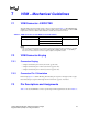
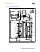
7.4 Mechanical Dimensions - PROPOSED
The mechanical dimensions for the VRM 10.2 module and connector are shown in Figure 7-1.
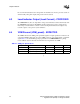
7.4.1 Gold Finger Specification
The VRM board must contain gold lands (fingers) for interfacing with the VRM connector that is
1.50 mm ±0.2 mm [0.059” ±0.008”] wide by 6.00 mm [0.236”] minimum long and spaced
2.50 mm [0.098”] apart. Traces from the lands to the power plane should be a minimum of
0.89 mm [0.035”] wide and of a minimal length.
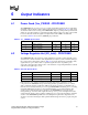
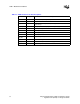
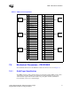
Table 7-3. VRM 10.2 Pin Assignments
1 VIN− 54 VIN+
2 VIN− 53 VIN+
3 VIN− 52 VIN+
4 VID4 51 VID3
5 VID2 50 VID1
6 VID0 49 VID5
7 VO-SEN+ 48 VO-SEN−
8 Vcc_PWRGD 47 VR_Hot#
9 OUTEN 46 LL0
10 Load_current 45 LL1
11 Unspecified 44 Unspecified
12 VRM_Pres 43 Unspecified
13 VO+ 42 VO+
14 VO+ 41 VO+
15 VO+ 40 VO+
16 VO− 39 VO−
17 VO− 38 VO−
18 VO− 37 VO−
19 VO+ 36 VO+
20 VO+ 35 VO+
21 VO+ 34 VO+
22 VO− 33 VO−
23 VO− 32 VO−
24 VO− 31 VO−
25 VO+ 30 VO+
26 VO+ 29 VO+
27 VO+ 28 VO+
KEY
KEY
KEY
KEY
KEY
KEY