
Manual

Specifications
Specifications subject to change without notice.
Maximum Distance* 2500 feet
Bandwidth 20 Hz to 20 kHz
Impedance 600 ohms, balanced
Isolation 500 V
Nominal Level 1.0 volts
Insertion Loss 1 dB
Common Mode Rejection Greater than 40 dB
Unshielded Twisted Pair Maximum capacitance: 20 pf/foot
Cabling Specifications Impedance: 100 ohms @ 1 MHz
(24 gauge or lower solid Attenuation: 6.6 dB/1000 ft. @ 1 MHz
copper) Cat 3, Cat 5, Cat 5e, Cat 6, Cat 7 compatible
Connectors Two (2) female RCA to one (1) RJ45
RJ45 Pinout Channel 1 (R): 1 & 2, pair 2
Channel 2 (L): 3 & 6, pair 3
Temperature Operating: 32 to 131 F (0 to 55 C)
Storage: -4 to 185 F (-20 to 85 C)
Humidity: up to 95%
Enclosure Black plastic
Dimensions 4.3” x 2.5” x 1”
Weight 0.2 lbs (3.2 oz.)
Ordering Information AVO-A2: single AVO-A2 balun in bulk packaging
AVO-A2-PAC: two AV0-A2 baluns in retail-ready packaging
Warranty 2 years
* Distances and picture quality may be affected by cable grade, cable quality, source and
destination equipment, RF and electrical interference, and cable patches. Intelix specifications are
based on straight-through cabling with standard-grade Cat 5.
Contact Information
Intelix
2222 Pleasant View Road
Middleton, WI 53562
Toll-free: 866-4-MATMIX
Phone: 608-831-0880
Fax: 608-831-1833
www.intelix.com
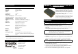
Intelix AVO-A2 Stereo Audio Balun
InsIns
InsIns
Ins
tt
tt
t
allation Manualallation Manual
allation Manualallation Manual
allation Manual
The Intelix AVO-A2 balun passively transmits two
mono or one stereo analog audio signal via Cat 5
unshielded twisted pair (UTP) cable, such as Cat 5.
Used in pairs, the AVO-A2 transmits analog audio in
either direction up to 2500 feet, providing a low-cost,
versatile cabling solution which uses a building’s
existing structured cabling system
The AVO-A2 is ideal for corporate AV, houses of
worship, schools, auditoriums, and virtually any other
situation involving structured audio distribution
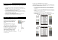
To install an AVO-A2 balun, perform the following steps:
1. Turn off power and disconnect the audio equipment by following the manufacturer’s
instructions.
2. Make certain that outlets and cross connects to which you will connect the AVO-A2
are configured properly and labeled appropriately to identify the circuit.
3. Verify the desired twisted pairs are not being used for other LAN or telephony
equipment.
4. Connect the RCA inputs from the source equipment to one of the two baluns. Two
AVO-A2’s are needed—one at each end of the run—and are interchangeable.
5. Connect a 4-pair Cat 5 cable from the RJ45 8-position modular jack of the AVO-A2
to a structured cable, such as Cat 5.
6. Connect the second balun’s RCA inputs to the destination equipment.
7. Connect the 4-pair Cat 5 cable from the RJ45 8-position modular jack of another
AVO-A2 to the structured cable attached to the first balun.
8. Power on the source and destination equipment and test for correct operation.
Installation
Caution: Do not attempt to open the balun housing. There are no user-serviceable parts
inside the AVO-A2. Opening the unit will void your warranty.
Caution: Do not connect the AVO-A2 to a telecommunication outlet wired to unrelated
equipment. Making such a connection may damage the equipment and/or
balun. Please ensure all wiring is “straight-through.”
Caution: Do not mount the balun over equipment ventilation openings. Covering the
openings may cause the equipment to overheat.
AvoCat
Series