
Instruction Manual

VGA2-SW4 Installation Guide
8001 Terrace Ave. Phone: 608-831-0880
Suite 201 Toll-Free: 866-462-8649
Middleton, WI 53562 Fax: 608-831-1833
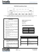
VGA2-SW4 Installation Guide
The Intelix VGA2-SW4 is a four input, one output RGB/YPbPr and stereo audio switcher. The VGA2-SW4 supports VGA, SVGA,
XGA, SXGA, UXGA (1600x1200), WUXGA (1920x1200), 480i, 576i, 480p, 576p, 720p, 1080i, and 1080p.
Troubleshooting
Symptom
Possible Solutions
No signal
Check VGA and audio cables for damage. Make
sure cables are of good quality and in good
condition.
Verify source and destination VGA ports are
operational.
Poor image and/or sound
Check VGA and audio cable quality.
Use shorter cables.
Unusual colors in the video
Verify VGA connectors are in good condition,
with no bent or missing pins.
Instructions
1. Turn off power to sources and destination
device according to the manufacturer’s
instructions.
2. Connect the video outputs of the source
devices to the VGA2-SW4 VGA inputs with
high quality HD15 cables.
3. Connect the audio outputs of the source
devices to the VGA2-SW4 audio inputs with
3.5mm cables.
4. Connect the video input of the destination
device to the video output of the VGA2-SW4
with high quality HD15 cables.
5. If the VGA2-SW4 will be controlled by a third-
party control system, connect a DE9 cable to
the RS232 port
6. Connect the included power supply to the
5VDC connector.
7. Power on connected sources and destination
device.
Important notice:
Do not attempt to disassemble or alter the
switcher housing. There are no user-serviceable
parts inside the unit. Doing so will void your
warranty.
To minimize the possibility of equipment damage
from electrostatic discharge (ESD), all source and
destination equipment must be powered off during
installation.
Allow proper ventilation to reduce the risk of
thermal failure.
RS232 Transmission Format:
Baud Rate: 9600 bps
Data Bit: 8 bits
Parity: None
Stop Bit: 1 bit
ALL RS232 COMMANDS MUST CONCLUDE
WITH A CARRIAGE RETURN AND LINE FEED.
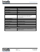
Command Code
Comment
“I” + “1”
Port 1 On
“I” + “2”
Port 2 On
“I” + “3”
Port 3 On
“I” + “4”
Port 4 On
“P” + “1”
Power On
“P” + “0”
Power Off