TM T intelligent motion systems, inc.
The information in this book has been carefully checked and is believed to be accurate; however, no responsibility is assumed for inaccuracies. Intelligent Motion Systems, Inc., reserves the right to make changes without further notice to any products herein to improve reliability, function or design. Intelligent Motion Systems, Inc.
Table of Contents Part 1: General Information And Hardware Information Section 1.1: Introduction to the MDrive17 Motion Control ....................................................................................................................... 5 Introduction to the MDrive17 Motion Control ................................................................................................................................................................................ 5 Feature Summary .......................
Variables ............................................................................................................................................................................................................................ 30 Math Functions .................................................................................................................................................................................................................. 31 Motion Commands .................................
Part 1: General Information and Hardware Specifications 3
Intentionally Left Blank 4
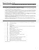
Section 1.1 Introduction to the MDrive17 Motion Control Introduction to the MDrive17 Motion Control The MDrive17 Motion Control offers the system designer a low-cost, intelligent motion controller integrated with a NEMA 17 high torque stepping motor and a +12 to +48 VDC microstepping drive.
Section 1.2 MDrive17 Motion Control Specifications Section Overview This section contains mechanical, motor and electrical specifications specific to each version of the MDrive17 Motion Control.
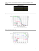
M D r i v e M o t i o n C o n t r o l 1 7 1 5 M o t o r S p e c s a n d S p e e d / To r q u e C u r v e s MDI1715 Holding Torque oz-in (N-cm) 60 (42.4) Detent Torque oz-in (N-cm) 2 2.5 (1.8) 2 Rotor Inertia oz-in-sec (kg-cm ) Weight (Motor+Driver) oz (gm) 0.00080 (0.057) 10.42 (295.4) Table 1.2: Rotary MDI1715 Motor Specifications Figure 1.
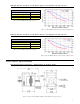
Linear Actuator MDrive Motion Control 1713 Specs and Speed-Force Curves MDI17 Linear Actuator Maximum Thrust lbs (kg) Maximum Screw Deflection Backlash inches (mm) Weight (Motor+Driver) oz (gm) 50 (22.7) ±1° 0.005 (0.127) 9.2 (0.127) Table 1.4: Linear Actuator MDrive17 Motion Control Motor Specifications Speed-Force Curve: 24 VDC Refer to Table 1. 5 for screw pitch information Figure 1.6: Speed-Force Curve - 24VDC (100% Current) Speed-Force Curve: 45 VDC Refer to Table 1.
MDrive17 Motion Control ACME Screw WARNING: The maximum axial load limit for the MDrive17 Linear motor is 50 lbs (22.7 kg). Do not exceed this rating! WARNING: The ACME Screw MUST NOT deflect more than ± 1 degree perpendicular to the motor face. Additional support for radial loads may be required! MDI17 ACME Screws Screw Travel/Full Step - Inches (mm) A 0.00125 (0.3175) B 0.000625 (0.015875) C 0.0003125 (0.079375) D 0.00015625 (0.00396875) Table 1.
General Specifications Software Program and Data Storage ......................................................................................... Non-Volatile User Program Space .................................................................................................. 767 Bytes User Registers ........................................................................................................... 4 - 32 Bit Math Functions ..........................................................................
Section 1.3 Introduction to the MDrive23 Motion Control Introduction to the MDrive23 Motion Control The MDrive23 Motion Control offers the system designer a low-cost, intelligent motion controller integrated with a NEMA 23 high torque stepping motor and a +12 to +48 VDC microstepping drive.
Section 1.4 MDrive23 Motion Control Specifications Section Overview This section contains mechanical, motor and electrical specifications specific to each version of the MDrive23 Motion Control. Shown are: Rotary Motor Specifications ! ! Linear Motor Specifications ! General Specifications ! Power Supply Requirements ! Thermal Specifications Rotary Motor Specifications Mechanical Specifications - Dimensions in Inches (mm) Interface Option 1.625 (41.28) 1.500 (38.10) 4 x Ø 0.205 (5.21) ±.010 (.
M D r i v e M o t i o n C o n t r o l 2 2 2 2 M o t o r S p e c s a n d S p e e d / To r q u e C u r v e s MDI2222 5.6 (3.92) 2 Rotor Inertia oz-in-sec (kg-cm ) 0.0037 (0.26) Weight (Motor+Driver) oz (gm) 24.4 (691.7) Torque in Oz - In Detent Torque oz-in (N-cm) 99 120 85 100 71 80 56 Table 1.
Linear Actuator MDrive Motion Control 2218 Specs and Speed-Force Curves MDI23 Linear Actuator Maximum Thrust lbs (kg) 200 (90.7) Maximum Screw Deflection ±1° Backlash inches (mm) 0.005 (0.127) Weight (Motor+Driver) oz (gm) 20.4 (578.3) Table 1.
MDrive23 Motion Control ACME Screw WARNING: The maximum axial load limit for the MDrive23 Linear motor is 200 lbs (90.7 kg). Do not exceed this rating! WARNING: The ACME Screw MUST NOT deflect more than ± 1 degree perpendicular to the motor face. Additional support for radial loads may be required! MDI23 ACME Screws Screw Travel/Full Step - Inches (mm) F 0.002 (0.0508) A 0.001 (0.0254) B 0.000833 (0.0211582) C 0.0005 (0.0127) D 0.0004167 (0.00793750) E 0.0003125 (0.0079375) Table 1.
General Specifications Software Program and Data Storage ......................................................................................... Non-Volatile User Program Space .................................................................................................. 767 Bytes User Registers ........................................................................................................... 4 - 32 Bit Math Functions ..........................................................................
Part 2: Connecting, Configuring and Programming the MDrive Motion Control 17
Intentionally Left Blank 18
Section 2.1 Interfacing the MDrive Motion Control Section Overview This section will acquaint the user with connecting and using the MDrive Motion Control. Layout and Interface Guidelines ! ! Pin Configuration and Descriptions ! Interfacing Power ! Interfacing RS-485 Communications ! Interfacing Digital I/O ! Interfacing Analog Input Layout and Interface Guidelines Logic level cables must not run parallel to power cables.
Connector P2 - 10 Pin Header Pin # Function Description 1- 5 N/C Reserved 6 RX+ RS-485 Receive + 7 RX- RS-485 Receive - 8 TX- RS-485 Transmit - 9 TX+ RS-485 Transmit + 10 GND Communications Ground Table 2.2: P2 Pin Configuration and Description Interfacing Power An advantage of the MDrive Motion Control is that only a single +12 to +48VDC unregulated linear or unregulated switching power supply is required to power the control circuitry and motor power.
Multiple MDrive Motion Control System (Party Mode) In systems with multiple controllers it is necessary to communicate with the control modules using party mode (PY=1) of operation. The MDrive Motion Control nodes in the system are configured in software for this mode of operation by setting the Party Flag (PY) to True (1). It is necessary for all of the nodes in a system to have this configuration selected.
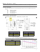
Interfacing the Digital I/O The MDrive Motion Control comes standard with a set of four (4) open collector +5 to +24VDC I/O point which may be programmed individually as either general purpose or dedicated inputs or outputs, or collectively as a group. The digital I/O may be defined as either active HIGH or active LOW. When the I/O is configured as active HIGH, the level is +5 to +24 VDC and the state will be read/set as a “1”. If the level is 0 VDC then the state will be read/set as “0”.
Interfacing Inputs as a Group Example MDrive23 Motion Control +5VDC PIN 1 Sample Software Configuration 'set inputs to user inputs active low, S1=0,0 S2=0,0 S3=0,0 S4=0,0 PR IN 'Read BCD State of Input Group Figure 2.
Interfacing Outputs The MDrive Motion Control Outputs may be configured as either general purpose or set to one of two dedicated functions, Fault or Moving. These outputs will sink up to 700 mA max and may be connected to +5 to +24VDC. Note that a current limiting resistor may be required to limt the current to 700 mA. As with the inputs the MDrive Motion Control Outputs may be used singularly or collectively as a group.
Interfacing the Analog Input The analog input of the MDrive Motion Control is a 0 to 5V, 10 bit resolution input. This offers the user the ability to receive input from temperature, pressure or other forms of sensors, and then control events based upon the input. The value of this input will be read using the I5 instruction, which has a range of 0 to 1024, where 0 = 0 volts and 5 = 5.0 volts. You may then use the program branch (BR) or subroutine call (CL) instructions to control events within the system.
Section 2.2 MDrive Motion Control Software Introduction Section Overview This section will acquaint the user with basics of MDrive Motion Control Programming Installing IMS Terminal Software ! ! Upgrading the MDrive Firmware ! The MDrive Program I n s t a l l i n g a n d U s i n g I M S Te r m i n a l System Requirements ! ! ! ! IBM Compatible PC. Windows 95/98 or Windows NT4.0 SP6, Windows 2000 SP2, Windows XP 10 MB hard drive space. A free serial communications port.
1) 2) 3) 4) 5) 6) 7) 8) To open the IMS Terminal select Start > Programs > IMS Terminal > IMS Terminal. Click the File Menu Item “Edit>Preferences”. Click the “Comm Settings” tab. Select the Communications Port that you will be using with your MDrive Motion Control. The BAUD rate is already set to the MDrive Motion Control default. Do not change this setting until you have established communications with the MDrive Motion Control. The “Window Size” settings are strictly optional.
Setting the Programmable Function Keys The IMS Terminal features the capability of programming up to 10 function keys, a feature typically found in more advanced terminal programs. These can be set to provide quick access to commonly used MDrive Immediate mode commands, execute programs, or even hold entire MDrive programs as there is no character limit for each function. A fly-out dialog can be brought up by clicking the arrow on the right of the function key “Contents” field.
MDrive Motion Control Programming The MDrive programming language consists of simple 1-2 character mnemonics. Operational Modes There are two operational modes for the MDrive. Immediate and Program: 1] 2] Immediate: Commands are issued and executed directly to the MDrive Motion Control by user entry into the terminal window. Program: Commands and processes are run from within an MDrive program. This mode is also used for program entry.
Flags Flags show the status of an event or condition. A flag will only have one of two possible states: either 1 or 0. Unlike variables, there are only factory defined flags. Factory Defined Flags Factory defined flags are predefined at the factory and cannot be deleted. When a FD (Factory Defaults) instruction is given, these flags will be returned to their factory default state. There are two types of factory defined flags: . . Read/Writable: This type of flag is user alterable.
Math Functions Another powerful feature of the MDrive Motion Control is its ability to perform common math functions and to use these to manipulate data. Addition .................................................................... K2†=P+R2 Subtraction ................................................................. K3†=R1-P Multiplication .............................................................. A=A*2 Division .........................................................................
I/O Commands S<1-4> This command configures the Type and Active state of I/O points 1-4. Using the PR command to read IO parameters Read IO1 Setup – “PR S1” Read IO2 Setup – “PR S2” Setting the I/O parameters Set IO 3 parameters – “S3=0,1” Sets IO3 as a General Purpose Input, Active High For example: To set IO4 as a Jog+ Input/Active Low S4 =7,0 I<1-4> Used to read the state of an individual input. PR I1 will read the state of input 1 and display it to the terminal window.
LB The MDrive Motion Control also offers the user the convenience of naming programs, subroutines and processes to ease in branching from one part of a program to another, or calling a subroutine. These labels, once set, will act as pointers to locations in program memory space. The LB, or Label Instruction, allows the user to assign a 2 character name to a program or branch process within a program or subroutine.
H Delays program execution in milliseconds. Switches to program mode at address 200 PG 200 Label command will name the program LB K1 xxxxx Program named by LB command xxxxx Delay 2 seconds between re-execution of program H 2000 Unconditional branch to K1 BR K1 xxxxx Designates the end of the program E Switches out of program mode P PRINT Outputs specified text and parameter values to a terminal or terminal software on a Host PC.
Section 2.
I / O I n s t r u c t i o n s , Va r i a b l e s a n d F l a g s Mnemonic Function Unit Range Syntax Example D1 D2 Set Input 1 Digital Filtering Milliseconds 0-255 D1=
P o s i t i o n R e l a t e d I n s t r u c t i o n s , Va r i a b l e s a n d F l a g s Mnemonic Function C1 Set Counter 1 HM Home to Home Switch P Set/Read Position PC Read Captured Position at Trip TP Trip on Position TE Trip Enable Unit Range Motor Counts Signed 32 bit Type 1-4 Motor/Encoder Counts Signed 32 bit Position - See Table <1-4> Syntax Example C1= HM P= TP , TE= Encoder Related Instructions, Variables and Flags Mnemonic Funct
Section 2.4 MDrive Motion Control Command Set MNEMONIC FUNCTION A TYPE Acceleration Motion Variable DESCRIPTION The A Variable sets the peak acceleration that will be reached by the MDrive in steps per second2.
MNEMONIC FUNCTION TYPE BR Branch Program Instruction DESCRIPTION The branch instruction can be used to perform a conditional or unconditional branch to a routine in an MDrive program. It can also be used to perform loops and IF THEN logic within a program. There are two parameters to a branch instruction.
MNEMONIC FUNCTION C2 TYPE Set Counter 2 (Encoder Counts) Motion Variable DESCRIPTION This variable contains the raw count representation of the integral 512 line encoder.
MNEMONIC FUNCTION D1-D5 TYPE Digital Input Filtering I/O Variable DESCRIPTION This variable will set the digital filtering to be applied to the selected input 1 - 5. The input must be stable for “time” amount of milliseconds before a change in state is available.
MNEMONIC FUNCTION DE TYPE Drive Enable Flag Setup Flag DESCRIPTION The DE flag enables or disables the drive portion of the MDrive Motion Control. USAGE DEFAULT 1 (Enabled) DE= <0/1> EXAMPLE: DE=0 DE=1 ‘Disable drive ‘Enable drive RELATED COMMANDS: — MNEMONIC FUNCTION DN TYPE Device Name Setup Variable DESCRIPTION The DN Variable stores the device name to be used when the MDrive is to be addressed in party mode operation.
MNEMONIC FUNCTION EE Encoder Enable Flag TYPE Setup Flag DESCRIPTION The EE flag enables or disables the optional encoder mode of the MDrive Motion Control. USAGE DEFAULT 0 (Disabled) EE= <0/1> EXAMPLE: EE=0 EE=1 ‘Disable encoder mode ‘Enable encoder mode RELATED COMMANDS: DB, C2, SF, SM, ST MNEMONIC FUNCTION EM Echo Mode Flag TYPE Setup Flag DESCRIPTION The Echo Mode Flag will set the full/half duplex configuration of the RS-485 channel. 0=Full Duplex (default), 1=Half Duplex.
MNEMONIC FUNCTION ER Error Number Variable TYPE Status Variable DESCRIPTION The ER variable indicates the program error code for the most recent error that has occurred in the MDrive Motion Control. The ER variable must be read in order to clear the EF flag. See Appendix A of this document for a complete listing of MDrive Motion Control Error Codes.
MNEMONIC FUNCTION H TYPE Hold Program Execution Program Instruction DESCRIPTION The hold instruction is used in a program to suspend program execution. If no parameter is specified the execution of the program will be suspended while motion is in progress. This will typically be used following a MA or MR instruction.
MNEMONIC HM FUNCTION TYPE Home to Home Switch Variable Setup Variable DESCRIPTION This instruction will find the selected I/O switch. There are four types for this command: 1) Speed (S): Specifies the direction and speed that the axis will move until the switch is activated (VM). 2) Creep (C): Specifies the direction and speed that the axis will move off the switch until it becomes inactive again (VI). When HM is executed, the axis moves in the direction specified by the sign of speed at VM.
MNEMONIC FUNCTION I5 Read Analog Input TYPE I/O Variable DESCRIPTION This variable will read the value of the voltage seen on the Analog Input. Can be used with PR (Print), BR (Branch) and Cl (Call Subroutine) instructions. The value read will between 0 and 1028.
MNEMONIC FUNCTION IN Read Inputs 1-4 As 1 Value TYPE I/O Variable DESCRIPTION This keyword will read the binary state of inputs 1-4 and print them as a decimal value. When used thus Input 1 is the Least Significant Bit (LSB), Input 4 is the Most Significant Bit (MSB). It may be used in conjunction with the R1-R4 (User Registers), PR (Print), BR (Branch) and Cl (Call Subroutine) instructions.
MNEMONIC FUNCTION L List Program Space TYPE Instruction DESCRIPTION The L instruction will print the contents of program space beginning at the specified address to the end. If no address is specified it will list beginning at line 1.
MNEMONIC MA FUNCTION Move To Absolute Position TYPE Motion Instruction DESCRIPTION Set mode for absolute move and move to an absolute position. MD (Current Mode) will be set to MA.
MNEMONIC FUNCTION MS TYPE Microstep Resolution Motion Variable DESCRIPTION The MS variable controls the microstep resolution of the MDrive Motion Control. There are 14 parameters that can be used with this variable, 8 binary and 6 decimal. The table below illustrates the parameter settings and their associated resolutions for the 1.8° stepping motor used with the MDrive Motion Control. The MS parameters given in the table below are the only valid parameters that will be accepted by the MDrive.
MNEMONIC MT FUNCTION TYPE Motor Settling Delay Time Motion Variable DESCRIPTION Specifies the motor settling delay time in milliseconds. MT allows the motor to settle following a move. This is the time between moves if consecutive motions are executed.
MNEMONIC FUNCTION OT Set Ouputs 1-4 As 1 Value TYPE I/O Variable DESCRIPTION The OT variable allows the user to set Outputs 1-4 as one 4 bit binary value. The value is entered in decimal, with a range of 0-15 and will display in binary where Output 1 will be the LSB and Output 4 will be the MSB.
MNEMONIC FUNCTION PM Postition Maintenance Enable TYPE Setup Flag DESCRIPTION This flag will enable the position maintenece functions of an MDrive Motion Control with encoder. The position maintenance velocity will be at the setting for VI (Initial Velocity).
MNEMONIC FUNCTION PS Pause Program Instruction TYPE Instruction DESCRIPTION This instruction is used to pause an executing program. Immediate mode instructions are allowed while a program is in a paused state. To resume the program the RS instruction is used. USAGE PS EXAMPLE: PS RELATED COMMANDS: RS MNEMONIC FUNCTION PY Party Mode Enable Flag TYPE Setup Flag DESCRIPTION The party flag will be set to 1 if the MDrive Motion Control is being used in a multidrop system.
MNEMONIC FUNCTION R1 - R4 TYPE User Registers User Variable DESCRIPTION The MDrive Motion Control has four 32 bit user registers to contain numerical data. These registers may contain up to 11 digits including the sign and may be used to store and retrieve data to set variables, perform math functions, store and retrieve moves and set conditions for branches and subroutine calls.
MNEMONIC FUNCTION RS Resume Program Instruction TYPE Instruction DESCRIPTION This instruction is used to resume a program that has been paused using the PS instruction. USAGE RS EXAMPLE: RS RELATED COMMANDS: PS MNEMONIC FUNCTION RT Return From Subroutine TYPE Instruction DESCRIPTION This instruction defines the end of a subroutine. This instruction is required and will be the final instruction in the subroutine executed by the CL instruction.
MNEMONIC FUNCTION S1 - S4 TYPE Set/Print I/O Point Type/Active State I/O Instruction DESCRIPTION This instruction is used to setup the I/O type and active states for I/O points 1 - 4. Each of MDrive Motion Control I/O points 14 may be programmed as either general purpose inputs and outputs, or to one of nine dedicated input functions or one of two dedicated output functions.
MNEMONIC FUNCTION SF TYPE Stall Factor Variable Encoder Variable DESCRIPTION If the encoder is enabled (EE = 1) and the encoder differs from the motor by more than the specified factor, a STALL is indicated. If SM is set to 0, then the motor will be stopped when a STALL is detected. USAGE UNITS Encoder counts SF= EXAMPLE: SF=20 RANGE 0 to 65000 DEFAULT 10 ‘Set the stall factor to twenty counts. If the motor falls behind by more than 20 encoder counts a stall is detected.
MNEMONIC FUNCTION ST Read Only Stall Flag TYPE Encoder Flag DESCRIPTION The ST flag will be set to 1 when a stall is detected. It will be cleared upon execution of another motion command. USAGE PR ST BR , ST=1 CL , ST=1 EXAMPLE RESPONSE: ST=0 ST=1 ‘motor not stalled ‘motor stalled RELATED COMMANDS: EE, SF, ST MNEMONIC FUNCTION TE Trip Enable Flag TYPE Setup Flag DESCRIPTION This flag will enable or disable specified trip functions.
MNEMONIC TP FUNCTION Trip on Position TYPE Variable DESCRIPTION Sets up a position event (trip) for the specified position. There are two parameters for the TP variable. The first specifies the address of the subroutine that should be executed when the position is detected The second specifies the position which will cause the event.
MNEMONIC FUNCTION V TYPE Read Only Velocity Variable Motion Variable DESCRIPTION The velocity variable is used in conjunction with the PR (print) instruction to read the current velocity of the axis in counts per second. This variable can also be used with the BR and CL instructions to set a condition based upon a velocity. This variable can also be used in conjunction with the user registers to compute another velocity.
MNEMONIC FUNCTION VM TYPE Maximum Velocity Variable Motion Variable DESCRIPTION The VM variable specifies the maximum velocity in counts per second that the axis will reach during a move command USAGE UNITS Counts per sec VM= EXAMPLE: VM=51200 RANGE 1 to 5000000 DEFAULT 768000 ‘set max velocity to 51200 counts per second RELATED COMMANDS: VM MNEMONIC VR FUNCTION Read Only Firmware Version TYPE Factory Variable DESCRIPTION This variable is used in conjuction with the PR instructi
Appendix A A S C I I TA B L E Dec Hex Char Dec Hex 0 0 NUL 32 20 1 1 SOH 33 21 2 2 STX 34 3 3 ETX 4 4 5 Char Dec Hex Char Dec Hex Char 64 40 @ 96 60 ` ! 65 41 A 97 61 a 22 " 66 42 B 98 62 b 35 23 # 67 43 C 99 63 c EOT 36 24 $ 68 44 D 100 64 d 5 ENQ 37 25 % 69 45 E 101 65 e 6 6 ACK 38 26 & 70 46 F 102 66 f 7 7 BEL 39 27 ' 71 47 G 103 67 g 8 8 BS 40 28 ( 72 48 H 104 68 h 9 9 TA B 41 29
Appendix B Error Codes Error Code Fault 0 No Error I/O Errors 1 I/O1 Fault 2 I/O2 Fault 3 I/O3 Fault 4 I/O4 Fault 5 I/O5 Fault 6 An I/O is already set to this type. 7 Tried to set an Input or defined I/O. 8 Tried to set an I/O to an incorrect I/O type. 9 Tried to write to I/O set as input or is “TYPED”. 10 Illegal I/O number. Data Errors 20 Tried to set unknown variable or flag. 21 Tried to set an incorrect value. 22 VI set greater than or equal to VM.
TWENTY-FOUR MONTH LIMITED WARRANTY Intelligent Motion Systems, Inc., warrants its products against defects in materials and workmanship for a period of 24 months from receipt by the end-user. During the warranty period, IMS will either, at its option, repair or replace Products which prove to be defective.
P.O. Box 457, 370 N. Main Street Marlborough, CT 06447 U.S.A. Phone: 860/295-6102 Fax: 860/295-6107 Email: info@imshome.com Home Page: www.imshome.com WESTERN REGION IMS Motors Division and Western U.S. Technical Support 105 Copperwood Way, Suite H Oceanside, CA 92054 Phone: 760/966-3162 Fax: 760/966-3165 E-mail Motors Division: motors@imshome.com E-mail Western Tech Support: wtech@imshome.com Western U.S. Sales Management Phone: 949/707-0156 Fax: 949/707-0157 Email: wsales@imshome.