
- IMS MDrive17 Motion Control Operating Instructions


20
PIN 1
+12 to +48 VDC
Unregulated
Linear or
Unregulated
Switching
Power Supply
PWR GND
+VDC
OUTPUT
Shielded Twisted Pair 18 AWG
MDrive23 Motion Control
Earth
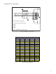
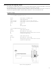
Table 2.2: P2 Pin Configuration and Description
Connector P2 - 10 Pin Header
Pin # Function Description
1- 5 N/C Reserved
6 RX+ RS-485 Receive +
7 RX- RS-485 Receive -
8 TX- RS-485 Transmit -
9 TX+ RS-485 Transmit +
10 GND Communications Ground
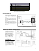
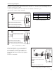
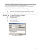
Interfacing Power
An advantage of the MDrive Motion Control is
that only a single +12 to +48VDC unregulated
linear or unregulated switching power supply is
required to power the control circuitry and motor
power.
A maximum of 2A output is required from the
supply for each MDrive. Note that the actual
power required will be based upon the load and
duty cycle.
Wiring should be accomplished using shielded
twisted pair Belden Part# 9740 or equivalent 18
Gauge. The shield should be attached to earth at
the power supply end and left floating at the
MDrive end.
Figure 2.1: Power Supply Interface
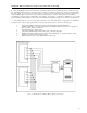
Interfacing RS-485 Communications
The MDrive Motion Control
communicates to the host using the
RS-485 protocol. Communications
may be configured as either half or
full duplex using the EM (Echo
Mode) Instruction. RS-485 may be
used in two ways: either to communi-
cate to a single MDrive Motion
Control, or to address up to 62
individually named MDrive nodes in a
multidrop system.
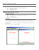
Single MDrive
Optionally available for the MDrive
Motion Control is a communications
cable, IMS P/N MD-CC200-000,
which has built-in RS-232 to RS-485
conversion circuitry. This will allow
you to connect the serial port of your
PC directly to the MDrive Motion
Control.
Figure 2.2: RS-485 Interface, Single MDrive Motion Control