
- IMS MDrive17 Motion Control Operating Instructions


25
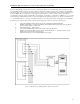
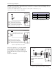
Interfacing the Analog Input
The analog input of the MDrive Motion Control is a 0 to 5V, 10 bit resolution input. This offers the user the ability to receive input
from temperature, pressure or other forms of sensors, and then control events based upon the input.
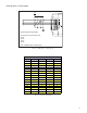
The value of this input will be read using the I5 instruction, which has a range of 0 to 1024, where 0 = 0 volts and 5 = 5.0 volts. You
may then use the program branch (BR) or subroutine call (CL) instructions to control events within the system.
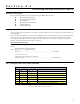
Sample Usage
‘*********Main Program***********
PG 100 ‘start prog. at address 100
LB A1 ‘label program A1
CL A2, I5<500 ‘Call Sub A2, If I5 is less than 500
CL A3, I5>524 ‘Call Sub A3, If I5 is greater than 524
BR A1 ‘loop to A1
E ‘End
PG ‘Exit program
‘*********Subroutines************
LB A2 ‘label subroutine A2
MA 2000 ‘Move Absolute 2000 steps
H ‘Hold program execution until motion ceases
RT ‘return from subroutine
LB A3 ‘label subroutine A3
MA -2000 ‘Move Absolute -2000 steps
H ‘Hold program execution until motion ceases
RT ‘return from subroutine
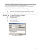
Figure 2.10: Analog Input Interface