
- IMS MDrive17 Motion Control Operating Instructions

32
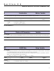
I/O Commands
S<1-4>
This command configures the Type and Active state of I/O points 1-4.
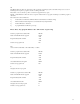
Using the PR command to read IO parameters
Read IO1 Setup – “PR S1”
Read IO2 Setup – “PR S2”
Setting the I/O parameters
Set IO 3 parameters – “S3=0,1” Sets IO3 as a General Purpose Input, Active High
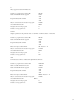
For example: To set IO4 as a Jog+ Input/Active Low
S4 =7,0
I<1-4>
Used to read the state of an individual input.
PR I1 will read the state of input 1 and display it to the terminal window.
BR K5, I2=0 will branch to the program address labled K5 when Input 2 is LOW
IN
Used to read the decimal equivalent of the 4 bit binary number represented by all 4 inputs collectively. Note the Input 4 is the Most
Significant Bit.
PR IN will print the decimal value of the inputs.
0<1-4>
Used to set the state of an output.
O2=1 will set Output 2 TRUE
OT
Used to set the 4 bit binary equivalent of the decimal number represented by all 4 outputs collectively. Note the Output 4 is the
Most Significant Bit.
OT=13 will set the outputs to 1101
System Instructions
The following System Instructions will be used frequently.
CP
The CP Instruction is used to clear Program memory space.
FD
The FD Instruction is used to return the MDrive Motion Control to its factory default state.
Program Instructions
PG
This instruction toggles the MDrive Motion Control into or out of program mode.
Switch to program mode at address 200 PG 200
xxxxx
Program starting at address 200 xxxxx
xxxxx
Switch out of program mode PG