T TM intelligent motion systems, inc. Excellence in Motion TM IM481H ULTRA MINIATURE HIGH PERFORMANCE MICROSTEPPING DRIVE OPERATING INSTRUCTIONS 370 N. MAIN ST., PO BOX 457, MARLBOROUGH, CT 06447 PH. (860) 295-6102, FAX (860) 295-6107 Internet: http://www.imshome.com, E-Mail: info@imshome.
The information in this book has been carefully checked and is believed to be accurate; however, no responsibility is assumed for inaccuracies. Intelligent Motion Systems, Inc., reserves the right to make changes without further notice to any products herein to improve reliability, function or design. Intelligent Motion Systems, Inc.
SECTION PAGE 1 LIST OF TABLES AND FIGURES ..................................... 1 2 INTRODUCTION ............................................................... 2 3 PIN ASSIGNMENT AND DESCRIPTION ........................... 3 4 ELECTRICAL SPECIFICATIONS ...................................... 4 5 THERMAL SPECIFICATIONS ........................................... 4 6 MECHANICAL SPECIFICATIONS 6.1 DIMENSIONAL IMFORMATION ........................................ 5 6.2 MOUNTING INFORMATION ......
LIST OF FIGURES Figure 1 DIMENSIONAL INFORMATION .............................. 4 Figure 2 MOUNTING INFORMATION .................................... 6 Figure 3 SETTING OUTPUT CURRENT ................................ 9 Figure 4 MOTOR CONNECTIONS ....................................... 12 Figure 5 POWER CONNECTIONS ......................................14 Figure 6 MICROSTEP RESOLUTION SELECTION ..............16 Figure 7 INPUTS .................................................................
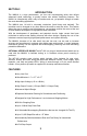
SECTION 2 INTRODUCTION The IM481H is a high performance, yet low cost microstepping driver that utilizes advanced hybrid technology to greatly reduce size without sacrificing features. The IM481H is exceptionally small, easy to interface and use, yet powerful enough to handle the most demanding applications. The IM481H has 14 built in microstep resolutions (both binary and decimal). The resolution can be changed at any time without the need to reset the driver.
SECTION 3 PIN ASSIGNMENT AND DESCRIPTION PIN # 1,2 PIN NAME PIN FUNCTION PHASE A Phase A of the stepping motor is connected between pin 1 and pin 2. See section 8. 3 CURRENT REDUCTION ADJUST Phase current reduction adjustment input. A resistor connected between this pin and pin 4 ( if used to set motor phase current ) will proportionately reduce current in both windings approximately .5 seconds after the last positive edge of the step clock input. See section 15.
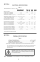
SECTION 4 ELECTRICAL SPECIFICATIONS Table 1 Test Parameters: TA = 25oC,+V = 48v TEST CONDITION MIN TYP MAX UNITS INPUT VOLTAGE ....................................................................................... 12 ....... 45 ........ 48* .......... V PHASE OUTPUT CURRENT ...................................... RMS .......................0.14 ...................1.5 .......... A PHASE OUTPUT CURRENT ..................................... PEAK ..................................................2.3 .......
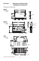
MECHANICAL SPECIFICATIONS SECTION 6.1 DIMENSIONAL INFORMATION Dimensions in Inches (mm) IM481H 2.700 (68.6) 2.450 (62.2) 2.225 (56.4) *Wt: 0.512 oz. 14.6 gms. 0.175 2 X Ø 0.150 (3.8)THRU 1.100 (27.9) 65° TYP. Heat Sink This Side 0.175 (4.4) 0.563 (14.3) PIN 1 0.225 (5.7) INT-481 0.058 (1.5) 0.016 (0.4) SQ. 0.100 (25.4) 3.000 (76.2) *Wt: 1.02 oz. 29.0 gms. 0.275 (6.99) 0.920 (23.37) 0.620 (15.75) 2.450 (62.
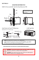
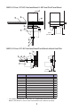
SECTION 6.2 MOUNTING INFORMATION IM481-H Driver and H-481 Heat Sink Direct Mount on PCB D NOTE: Components are described in the table on the following page. F *4 1 A B 3 C G 0.096 (2.43) PCB Hole Pattern for Direct PCB Mounting H-481 Heat Sink Dimensions are in Inches (mm) 0.063 (1.6) 0.240 (6.1) Ø 0.250 +0.003 / - 0.0 (6.35 +0.08 / - 0.0) 1.875 (47.63) Pin #1 0.100 Typ (2.54 Typ) 0.064 Pad, 0.031 Hole (1.6 Pad, 0.
IM481-H Driver, INT-481 Interface Board, H-481 Heat Sink Panel Mount 3 F E H *4 1 2 0.915 (23.25) Ref. C B A IM481-H Driver, INT-481 Interface Board Panel Mount without Heat Sink *4 1 A B C 2 0.180 (4.57) Ref. Product/Item # Description Qty. 1 IM481H Microstepping Driver 1 2 INT-481 Interface Board 1 1 3 H-481 Heat Sink 4 TI-481 Isolating Thermal Pad 1 A #6-32x5/8" Pan Head Screw 2 2 B #6 Split Lock Washer C #6 Flat Washer, 0.250" OD, 0.145" ID, 0.
OUTPUT CURRENT SECTION 7.1 DETERMINING THE OUTPUT CURRENT For any given motor, the OUTPUT CURRENT used for MICROSTEPPING is determined differently from that of a HALF/FULL STEP driver. In the IM481H, a sine/cosine output function is used in rotating the motor. Therefore, when microstepping, the specified phase current of the motor is considered an RMS value. The CURRENT ADJUSTMENT RESISTOR used to set the output current of the IM481H sets the peak output of the sine/cosine waves not the RMS value.
SECTION 7.2 SETTING OUTPUT CURRENT The OUTPUT CURRENT on the IM481H is set by applying a voltage to pin 5 (current adjustment). The output current is set as follows: PEAK OUTPUT CURRENT (Amps) = Volts applied to pin 5 EXAMPLE: 1.4 volts applied to pin 5 will set the peak output current of the IM481H to 1.4 amps per phase. To generate the reference voltage needed to set the peak output current of the driver, a 1mA current source is provided (pin 4, Current Reference ).
SECTION 7.3 RESISTOR TABLE Table 3 PEAK OUTPUT CURRENT (AMPS) REFERENCE (VOLTS) RESISTOR VALUE (1%) (OHMS) 0.20 ................................ 0.20 ............................. 200 0.25 ................................ 0.25 ............................. 249 0.30 ................................ 0.30 ............................. 301 0.35 ................................ 0.35 ............................. 348 0.40 ................................ 0.40 ............................. 402 0.45 ............
MOTOR SECTION 8.1 MOTOR SELECTION The IM481H is a Bipolar driver which works equally well with both Bipolar and Unipolar motors, ( i.e. 8 and 4 lead motors and 6 lead center tapped motors (see section 8.2, Connecting the Motor)). To maintain a given set motor current, the IM481H chops the voltage using a constant chopping frequency and a varying duty cycle. Duty cycles that exceed 50% can cause unstable chopping. This characteristic is directly related to the motor’s winding inductance.
MOTOR CONNECTIONS 1 1 2 2 PHASE A PHASE A PHASE B PHASE B 20 20 21 21 8 LEAD MOTOR SERIES CONNECTION 8 LEAD MOTOR PARALLEL CONNECTION 1 1 2 NC 2 NC PHASE A PHASE A PHASE B PHASE B NC 20 20 21 21 6 LEAD MOTOR HIGHER SPEED CONFIGURATION ( HALF COIL ) NC: NO CONNECTION NC 6 LEAD MOTOR HIGHER TORQUE CONFIGURATION ( FULL COIL ) NC: NO CONNECTION 1 2 PHASE A PHASE B 20 21 4 LEAD MOTOR Figure 4 12
POWER REQUIREMENTS SECTION 9.1 MOTOR POWER Pins 11 (ground), and 12 (+V) are used to connect the motor DC power to the IM481H. Two local capacitors are needed, connected between pins 11 and 12 and located as close to the pins as possible, to insure stable operation. The first capacitor is a low impedance, aluminum electrolytic. The continuous operating voltage of the capacitor should exceed the maximum supply voltage as well as any additional voltage caused by the motors back EMF.
SECTION 9.2 +5 VDC INPUT The IM481H requires an external regulated +5Vdc power supply. The supply is connected between pins 11 (ground), and 14 (+5vdc). A 22 microfarad 10v tantilum capacitor must be placed as close to the IM481H as possible between the +5vdc input pin (14) and ground. The +5vdc supply ground and the motor supply ground should not be connected together at the power supplies.
SECTION 10 LAYOUT AND INTERFACE GUIDELINES Logic level signals should not run parallel to motor phase signals. The motor phase signals will introduce noise into the logic level signals and can make the system unreliable. Motor phase signals should run as pairs and should be separated from other signals by ground traces where possible. When leaving the board, motor cables should not be run parallel with other wires and phases should be wired using twisted pairs.
MICROSTEP SELECTION Table 5 RESOLUTION (Microsteps/Step) STEPS/REV RESOLUTION (1.
SECTION 12 FULLSTEP OUTPUT SIGNAL The FULLSTEP output signal from the IM481H is an active high output at pin 18. This output is TRUE for the duration of the full step. A full step occurs when either Phase A or Phase B cross through zero (i.e. full current in one winding and zero current in the other winding). This fullstep position is a common position no matter what resolution is selected.
SECTION 14 INPUTS The inputs to the IM481H are internally pulled up to the +5VDC internal supply. Figure 7 shows the inputs and their associated pull up resistor values. See Section 4, Electrical Specifications, for resistor tolerence. Fault In Resolution Select 0 Resolution Select 1 Resolution Select 2 Resolution Select 3 Reset +5 VDC Step Clock Direction Enable An open collector output is recommended when interfacing with the IM481H.
SECTION 15 AUTOMATIC CURRENT REDUCTION Built into the IM481H is the ability to automatically reduce the current in the motor windings after the completion of a move. The reduction occurs approximately .5 seconds after the last positive going edge of the Step Clock input. The IM481H will then revert back to the original current setting at the next positive going edge of the Step Clock input.
SECTION 16 FAULT PROTECTION The IM481H is internally protected against over temperature, and over current. The over temperature set point is between 60 and 70 °C. Care should be taken when choosing and installing a heat sink so that there is a good thermal conduction, otherwise hot spots may occur in the IM481H which will reduce the operating thermal range. The over current protection consists of PHASE to PHASE, and +V to PHASE.
SECTION 18 OPTIONS/ACCESSORIES DESCRIPTION Thermal Pad PART NUMBER TI - 481 Interface Board INT-481 Heat Sink ( Includes mounting hardware ) H-481 21 Pin Right Angle Connector HY481-CN021 Small End Screw Driver SD1 21
APPENDIX A Recommended Cable Configurations: DC Supply to IMS Driver Cable length, wire gauge and power conditioning devices play a major role in the performance of your IMS Driver and Motor. NOTE: The length of the DC power supply cable to the IMS Driver should not exceed 50 feet. Example A demonstrates the recommended cable configuration for DC power supply cabling under 50 feet long.
Example B – Cabling 50 Feet or Greater, AC Power to Full Wave Bridge - + To Cable A NOTE: Connect the cable illustrated in Example A to the output of the Full Wave Bridge Full Wave Bridge Cable Length as required Shielded Twisted Pair (Wire Size from IMS Driver Supply Cable AWG Table) π Type RFI Filter ≥ Required Current Shield to Earth Ground on Supply End Only Transformer : 0 to 28 VAC RMS for 48 VDC Systems 20 to 48 VAC RMS for 75 VDC Systems 23
Example C – Cabling 50 Feet or Greater, AC Power to Power Supply DC Volts Out To Cable A + NOTE: Connect the cable illustrated in Example A to the output of the Power Supply - Power Supply Cable Length as required Shielded Twisted Pair (Wire Size from IMS Driver Supply Cable AWG Table) π Type RFI Filter ≥ Required Current Shield to Earth Ground on Supply End Only 120 or 240 VAC Dependent on Power Supply 24
NOTE: These recommendations will provide optimal protection against EMI and RFI. The actual cable type, wire gauge, shield type and filtering devices used are dependent on the customer’s application and system.
Recommended Cable Configurations: IMS Driver to Motor Cable length, wire gauge and power conditioning devices play a major role in the performance of your IMS Driver and Motor. NOTE: The length of the DC power supply cable between the IMS Driver and the Motor should not exceed 50 feet. Example A demonstrates the recommended cable configuration for the IMS Driver to Motor cabling under 50 Feet long.
Example B - Cabling 50 Feet or Greater, IMS Driver to Motor Phase A Phase A Phase B Phase B Ferrite Beads Cable Length 50 Feet or greater Two Shielded/Twisted Pairs (Wire Size from IMS Driver to Motor Cable AWG Table) Phase A Common Mode Line Filters (2x) Phase A Shield to Earth Ground on Supply End Only Phase B Phase B *L ≈ 0.5 MH * 0.5 MH is a typical starting point for the Common Mode Line Filters.
IMS Driver to Motor Cable AWG Table 1 Ampere (Peak) Length (Feet) 10 Minimum AWG 20 5 Amperes (Peak) 25 50* 75* 100* 20 18 18 Length (Feet) 16 2 Amperes (Peak) Length (Feet) 10 Minimum AWG 20 16 14 Length (Feet) 14 10 Minimum AWG 18 14 16 14 12 12 25 50* 75* 100* 14 14 12 12 7 Amperess (Peak) 25 50* 75* 100* 16 10 Minimum AWG 14 3 Amperes (Peak) Length (Feet) 25 50* 75* 100* 6 Amperess (Peak) 25 50* 75* 100* 18 10 Minimum AWG 16 12 Length (Feet) 12 10 Minimum AWG 12
This page intentionally left blank.
WARRANTY TWENTY-FOUR (24) MONTH LIMITED WARRANTY Intelligent Motion Systems, Inc. (“IMS”), warrants only to the purchaser of the Product from IMS (the “Customer”) that the product purchased from IMS (the “Product”) will be free from defects in materials and workmanship under the normal use and service for which the Product was designed for a period of 24 months from the date of purchase of the Product by the Customer.
P.O. Box 457, 370 North Main Street Marlborough, CT 06447 U.S.A. Phone: 860/295-6102 Fax: 860/295-6107 Email: info@imshome.com Home Page: www.imshome.com TECHNICAL SUPPORT Eastern U.S. Phone: 860/295-6102 Fax: 860/295-6107 E-mail: etech@imshome.com Western U.S. Phone: 760/966-3162 Fax: 760/966-3165 E-mail: wtech@imshome.com IMS MOTORS DIVISION 105 Copperwood Way, Suite H Oceanside, CA 92054 Phone: 760/966-3162 Fax: 760/966-3165 E-mail: motors@imshome.