A Higher Level of Precision… A Higher Level of Performance Intell-Print OM-192-S Dot Matrix Printer User Operation Manual 1
1. INTRODUCTION OM19X is a dot matrix impact printer that is available in 24 column, OM190, and 40 column, OM192, models. It is compact and reliable with a variety of features and options suitable for a wide array of applications including medical and industrial instruments, point of sale, test and measurement, security, time and attendance, etc. 1.
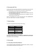
2. SPECIFICATIONS 2-1. General specifications. Model Print method No. of columns Printing speed No. of dots per line Dot Size Character size (mm) Line Spacing Font size Interface Emulation Data buffer Ink ribbon Paper No. of copies Power supply Dimensions (mm) Reliability (MCBF) Weight Safety approvals Operating condition OM190 OM192 Shuttle impact dot matrix (8 pins) 24 40 2.5 lps 1.7 lps 144 240 0.33 (H) x 0.38 (W) mm 1.7 (W) x 2.6 (H) 1.1 (W) x 2.
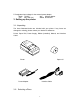
Z: Designates input voltage for the external power adaptor Blank 110VAC WA Without adaptor 220 220 –240 VAC SMPS 90-240VAC 3. Setting up the printer 3-1. Unpacking. The items illustrated below are included with your printer. If any items are damaged or missing, please contact your dealer for assistance. Printer, Paper Roll, Power Supply, Ribbon (installed), Manual, and Interface Cable. Printer Paper roll Power Adapter Interface Cable 3-2.
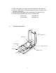
1. Protect your printer from excessive heat such as direct sunlight or heaters. 2. Avoid exposing the printer to excessive dust and humidity. 3. Place the printer on a firm, level surface free from intense vibration or shock. 3-3 Connecting the Power Adapter This printer requires an external power supply. Be sure to use a power supply that matches the specifications. 1. 2. 3. 4. Make sure the power switch is OFF. Insert the output plug of the power adapter into the DC jack of the printer.
3. Use a screw driver to fasten the cable screws to the two nut screws installed on the printer connector. 4. Connect the other end, DB9-F connector, to your computer. 5. Use Omniprint part number: CBL-625F-25M (DB-25 male on the host side) CBL-69F-25M (DB-9 male on the host side) 3-4-2 Parallel Interface Cable: OM19 -P 1. Make sure that both the printer and computer are turned off. 2. The parallel printer comes with a DB-25 male connector.
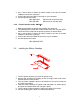
Regular Long Life ERC-09ERC-22- ( P for purple or B for black) ( P for purple or B for black) © 3-6 Loading Paper Use a paper roll that meets the specifications. Do not use paper rolls that are glued to the core. Make sure data is not being transmitted to the printer while loading paper. `````` PUSH ribbon change 1. Cut the leading edge of the paper roll straight at a right angle, as shown above. 2.
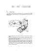
4. Hold the both edges of the paper and insert it straight into the paper slot. 5. Press the FEED button until approximately two inches of paper is fed through the mechanism. 6. Tear the excess paper against the serrated edge and close the cover. 7. Use the following Omniprint part number to reorder paper: PP-225-135 PP-225-90WC 4. 1 ply paper roll 2 ply paper roll External Appearance.
Interface connector DC Jack 5. Control Panel The control panel features four buttons and one LED to indicate printer status. ON BUTTON: Press the ON button to power up the printer. A red LED inside the button will light up. The printer goes ON LINE ready to receive data from the host. OFF BUTTON: Press the OFF button once to turn the power OFF. FEED BUTTON: When the FEED button is pressed and then released within 0.5 sec., the paper feeds only one line.
6. Running the Self Test Any time you want to check the performance of your printer you can run the self test described below. This shows whether your printer is working correctly. 1. While holding down the FEED button, turn the printer on. 2. The printer prints the model name, EPROM revision installed, and a few lines of the rotating character set. 3. The printer will automatically stop printing at the completion of the self test and enter the normal mode.
1. By turning the power on while pressing the SEL button the printer will print the current configuration and get in SET-UP mode. 2. The power LED will flash every second to indicate the printer is in SETUP mode. 3. By pressing the FEED button, in SET-UP mode, you can scroll through the printer parameters in the order shown in the table below. 4. Pressing the SEL button will cause the setting of a parameter to change in the sequence shown below. 5.
If the printer is turned on while pressing the SEL and FEED buttons, simultaneously, and only the SEL button is released, the printer will print : “nvr comms ready>” At this point the printer is waiting to receive data in the following format : SETUP mode + Carriage Return +n1+…n10 (n1 to n10 are hex number) the SET-UP mode followed by a carriage return indicates that the printer should expect parameter data as shown in the table below.
9. Accessories 1) Paper: 57.5mm+/-0.5mm(width) , 60mm max(roll diameter) , 85 microns (thickness) PP-225-80 1-ply paper roll PP-225-75WC 2-ply paper roll 2) Ribbon specification : ERC-09 P (Purple) or B (Black) Standard cartridge ERC-22 P (Purple) or B (Black) Long Life Cartridge 3) Interface Cable: 6 foot long, shielded cable with molded connectors. CBL-625M-25F-STR Parallel cable CBL-625F-25M Serial cable w/ DB-25F host side CBL-69F-25M Serial cable w/ DB-9F host side 4)Power Supply: Output: 9VDC 1.
PRINTED Make sure a ribbon cartridge is installed properly that is not worn out. Please note that the ribbon needs to be in front of the paper. If the printout is faint, turn the knob on the cartridge in the direction of the arrow. Also, see if the knob turns when the FEED button is pushed, if it does not, then the advance gear on the ribbon or the mechanism may be defective or worn out. 3)IF THE PRINTER DOES NOT COMMUNICATE WITH THE HOST. Run the self test to check that the printer works properly.
Input Control (DTR signal) : Mark: Data transmission not possible Space: Data transmission possible 11-1-2 Connector Pin Assignment FUNCTION RXD TXD CTS RTS DSR GND *POWER NC F-GND DTR PIN NUMBER 3 2 5 4 6 7,9,14 12,13,16 5,6,8,10,11,15,17-19,2125 1 20 INPUT-OUTPUT IN OUT IN OUT IN IN OUT * Please note that some models can be set at the factory to receive power through the serial port. 11-1-3 Serial Interface Timing Diagram 11-2.
PIN 1 2 3 4 5 6 7 8 9 10 11 12 13 FUNCTION STROBE DATA 0 DATA 1 DATA 2 DATA 3 DATA 4 DATA 5 DATA 6 DATA 7 ACK BUSY N.C. N.C. PIN 14 15 16 17 18 19 20 21 22 23 24 25 FUNCTION N.C. N.C. N.C. N.C. N.C. +9V +9V GND GND GND GND GND Printer is capable of receiving data from the host while the BUSY signal is in the LOW state and communication will be interrupted when the signal is HIGH> 12. COMMAND CODES 12.
REVERSE PRINT DOUBLE HEIGHT GRAPHICS CTRL Y CTRL Z CTRL [,n 19H 1AH 1BH, n 25 26 27,n 12.
CR(0DH) : This command prints the data in the print buffer and feeds one line. If a LF is sent immediately after CR, it will be ignored to avoid double printing. When the line buffer is full, ie th th upon receiving the 24 and 40 characters in the case of OM190 and OM192, respectively, the printer will automatically print the data in the buffer. If CR or LF is sent, they will be ignored in this situation.
CR(0DH) : This command prints the data in the print buffer and feeds one line. If a LF is sent immediately after CR, it will be ignored to avoid double printing. ESC ! n(1BH,21H,n) : Sets the print mode according to the following table. n is a single byte in which each bit sets the printing function. Note that underline cannot be used with a horizontal tab and any combination of double height and width can be used. Default is n=0.
11.2.3 COMMAND DESCRIPTION FOR CBM560 EMULATION LINE FEED (0AH) : Prints the data in the print buffer and feeds one line. FORM FEED(0CH) : Form feeds after printing. This is fixed at three lines. CR(0DH) : Feeds a new line after printing. REVERSE PRINT(14H) : This command causes the printer to print white on black. You can toggle between reverse and normal anywhere on a line but the reverse print mode will automatically be terminated at the end of a line.
APPENDIX 2.
APPENDIX 3.