
Printer User Manual


15
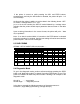
Input Control (DTR signal) : Mark: Data transmission not possible
Space: Data transmission possible
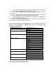
11-1-2 Connector Pin Assignment
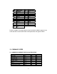
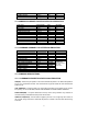
FUNCTION PIN NUMBER INPUT-OUTPUT
RXD 3 IN
TXD 2 OUT
CTS 5 IN
RTS 4 OUT
DSR 6 IN
GND 7,9,14
*POWER 12,13,16 IN
NC 5,6,8,10,11,15,17-19,21-
25
F-GND 1
DTR 20 OUT
*Pleasenotethatsomemodelscanbesetatthefactorytoreceivepowerthroughthe
serial port.
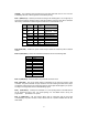
11-1-3 Serial Interface Timing Diagram
1 1-2. PARALLEL INTERFACE
11-2-1 Parallel Interface Specifications
Data Transmission Method: 8 bit parallel, DATA0
–DATA7
Synchronization: Via e
xternal STROBE pulses
Handshaking: ACK and BUSY signals
Data Transfer Rate: 1000 to 6000 characters per second
Logic Level: Compatible with TTL level
11-2-2 Parallel Connector Pin Assignment